Trigger Sprayer Nozzle Assembly with Pull/Push Foaming Tube

Inactive Publication Date: 2009-10-15
MEADWESTVACO CALMAR INC
View PDF9 Cites 12 Cited by
  • Summary
  • Abstract
  • Description
  • Claims
  • Application Information

AI Technical Summary

Benefits of technology

[0016]In addition to the above, the nozzle assembly of the invention includes the foamer tube that is mounted on the nozzle cap for rotation of the foamer tube with the nozzle cap. The foamer tube is also mounted to the nozzle cap for axial reciprocating movement between a retracted position and an extended position of the tube relative to the cap. In the retracted position of the tube, a cylindrical interior surface of the tube is positioned relative to the orifice of the nozzle cap where the spray pattern of liquid discharged from the orifice will bypass the tube interior surface and not come into contact with the tube interior surface. This allows the nozzle assembly to discharge liquid in a spray pattern. In the extended position of the foamer tube relative to the nozzle cap, the spray pattern of liquid discharged from the nozzle cap orifice will contact with the interior surface of the tube. The spray pattern of liquid contacting the interior surface of the tube g

Problems solved by technology

Individuals using this type of prior art nozzle assembly can find them difficult to use when a particular liquid discharge pattern is desired.
This require

Method used


Image

  • Trigger Sprayer Nozzle Assembly with Pull/Push Foaming Tube
  • Trigger Sprayer Nozzle Assembly with Pull/Push Foaming Tube
  • Trigger Sprayer Nozzle Assembly with Pull/Push Foaming Tube

Examples


Embodiment Construction

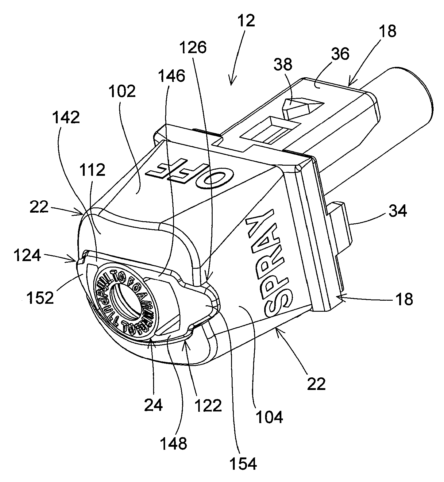
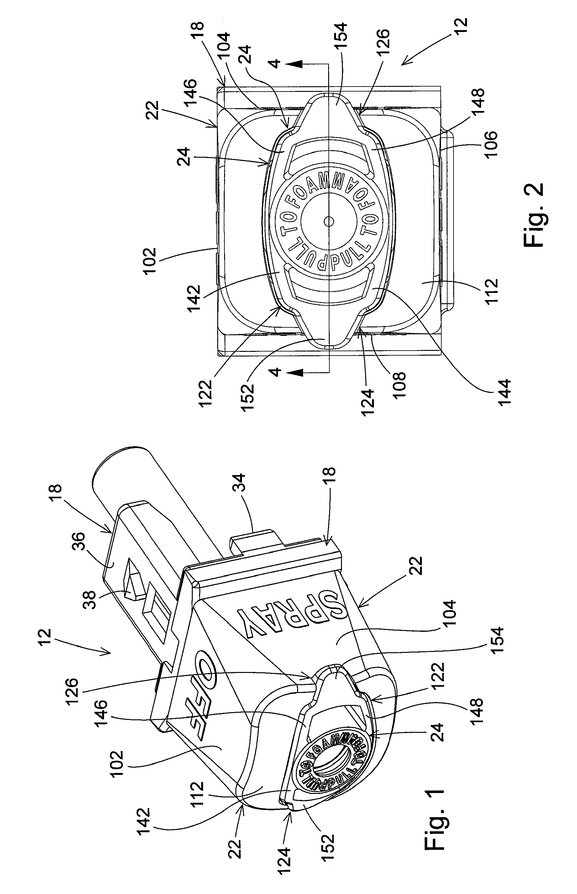
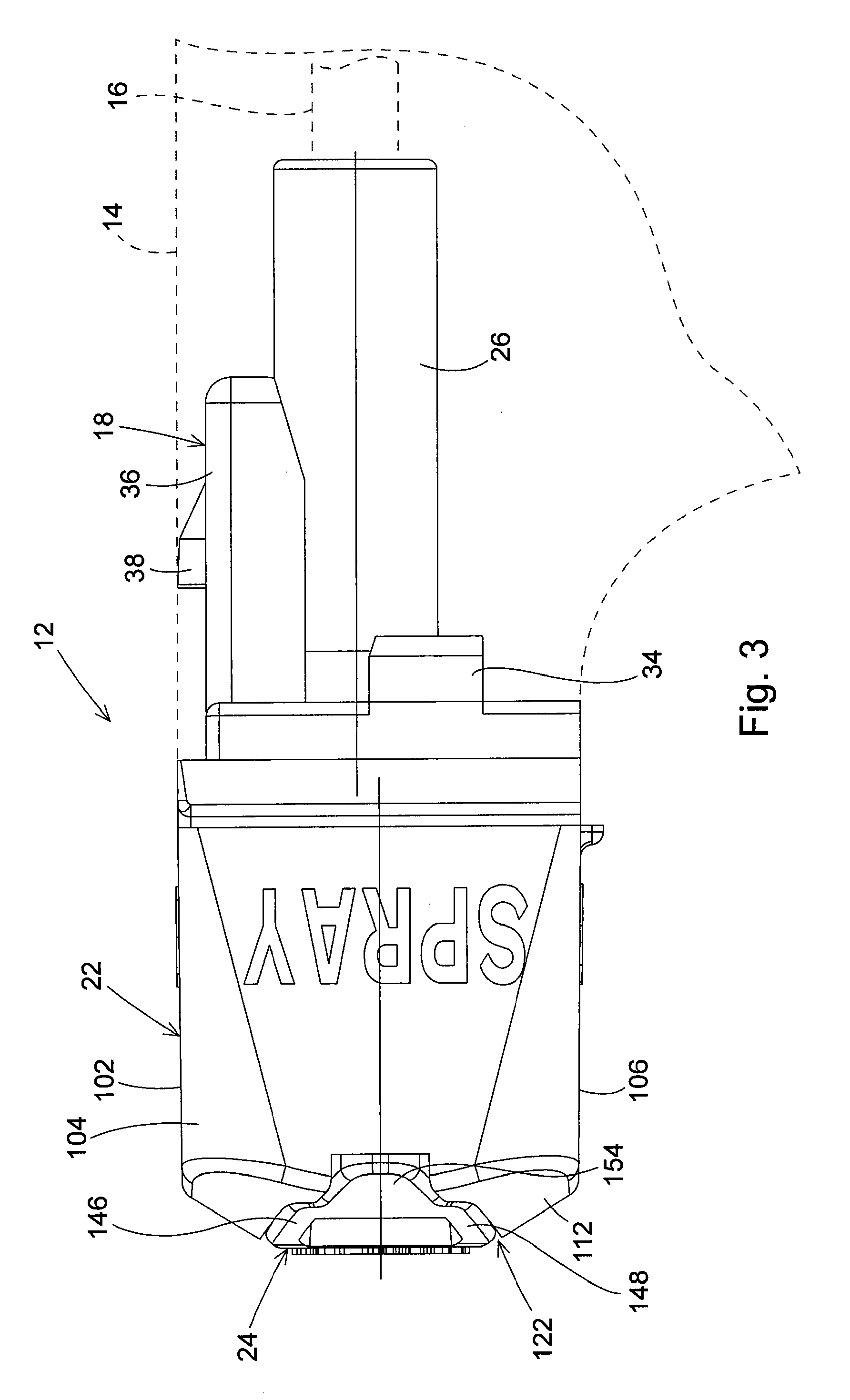
[0024]The trigger sprayer nozzle assembly of the invention is similar to, but has a more simplified construction than the nozzle assembly of the U.S. Patent of Foster et al. No. 6,557,783, which is assigned to the assignee of the present invention and is incorporated herein by reference. FIG. 1 is a perspective view of the nozzle assembly 12 of the invention removed from a trigger sprayer. FIG. 3 is a side view of the nozzle assembly 12 assembled to a trigger sprayer 14. The trigger sprayer 14 is shown in dashed lines in FIG. 2 because the nozzle assembly 12 of the invention is designed to be used with essentially any type of manually held and manually operated trigger sprayer that discharges liquid through the liquid discharge passage 16 of the sprayer. The nozzle assembly 12 is shown in FIG. 3 communicating with the liquid discharge passage 16 of the trigger sprayer 14. The nozzle assembly 12 is comprised of only three basic component parts. These include a nozzle base 18, a nozzl...


PUM


Abstract

An indexing nozzle assembly for a trigger sprayer is comprised of a nozzle base that is attachable to a sprayer housing of the trigger sprayer, a cap that is mounted for rotation on the nozzle base, and a foaming tube that is mounted for linear reciprocating movement on the cap. Rotation of the cap on the nozzle base changes liquid discharge from the trigger sprayer between an off condition and at least a spray condition. In the spray condition of the nozzle cap, the foaming tube can be manually pulled and extended from the nozzle cap. With the foaming tube extended from the nozzle cap, the liquid discharge from the nozzle assembly in a spray pattern comes into contact with an interior surface of the tube and generates a foam discharge from the nozzle assembly.

Description

BACKGROUND OF THE INVENTION[0001]1. Field of the Invention[0002]The present invention pertains to a handheld and hand operated liquid sprayer commonly called a trigger sprayer. In particular, the present invention pertains to an indexing nozzle assembly for a trigger sprayer that is comprised of a nozzle base that is attachable to a sprayer housing of the trigger sprayer, a cap that is mounted for rotation on the nozzle base, and a foaming tube that is mounted for linear reciprocating movement on the cap. With the nozzle base attached to the trigger sprayer housing, liquid discharged from the housing passes through the nozzle base. The rotation of the cap on the nozzle base changes the nozzle assembly between an off condition and a spray condition. In the spray condition of the nozzle cap, the foaming tube can be manually pulled and extended from the nozzle cap. With the foaming tube extended from the nozzle cap, liquid discharged from the nozzle assembly in a spray pattern comes in...

Claims


Application Information

Patent Timeline
IPC IPC(8): B05B1/12B05B9/043
CPCB05B1/3436B05B7/005B05B1/12B05B11/0032B05B11/3057B05B7/0425B05B11/1057
Inventor FOSTER, DONALD D.NELSON, PHILIP L.
Owner MEADWESTVACO CALMAR INC
Why Eureka
Try Eureka