
Inkjet printing apparatus and inkjet printing method

a printing apparatus and inkjet technology, applied in the direction of printing, other printing apparatus, etc., can solve the problems of increasing the ejection volume, the ejection volume is greatly affected, and the growth of bubbles is greatly affected, so as to stabilize the ejection volume of ink

Inactive Publication Date: 2009-10-15
CANON KK
View PDF9 Cites 0 Cited by
  • Summary
  • Abstract
  • Description
  • Claims
  • Application Information

AI Technical Summary

Benefits of technology

[0013]The present invention provides an inkjet printing apparatus and an inkjet printing method which can control the temperature of a print head and stabilize the ejection volume of ink to be ejected, even when a printing duty is high, so that a high-quality image can be printed.
[0018]According to the present invention, since the temperature of the print head is raised when the ink ejection volume for each unit printing area is increased, the optimal temperature around the ejection port is maintained while taking into account the heat exhausting effects that will be accompanied by the ejection of ink, and the ink ejection volume can be stabilized. As a result, a fluctuation of the ink ejection volume can be restricted, and a high-quality image can be provided.

Problems solved by technology

First, in the thermal inkjet printing system, thermal energy is generated by supplying power to heaters that produce ink bubbles for ejecting ink droplets, and in the event, the growth of bubbles is greatly affected by the temperature of the ink in the immediate vicinity of the heaters.
Therefore, in the thermal inkjet printing apparatus, since the ejection volume of ink is greatly affected by the temperature of the ink near the heater, there is a tendency to increase the ejection volume when the temperature of the ink is high, and to reduce the ejection volume when the temperature is low.
Not all of the thermal energy generated by the heater contributes to the generation of bubble.
However, since thermal energy is supplied by the heater during the printing operation, the temperature may continuously rise when the amount of the energy released is smaller than the amount of that supplied.
Especially when the ejection volume is fluctuated while an image is printed on the printing medium based on print data, there is a possibility of changing the dimensions of dots formed by the ink landed on the printing medium.
In this case, there is a possibility of giving rise to unevenness of the density distribution of images printed on a page to cause image deterioration.
In this case, when the ink ejection volumes of these nozzles are simply added together in accordance with the printing duty, the temperature of the print head cannot be accurately controlled.
Therefore, when the ink volumes ejected through the nozzles for 5 pl and 2 pl are simply added together, and the total ink volume is employed to select electric power for heating the print head from one table, temperature control for the print head is not appropriately performed.

Method used


Image

  • Inkjet printing apparatus and inkjet printing method
  • Inkjet printing apparatus and inkjet printing method
  • Inkjet printing apparatus and inkjet printing method

Examples


first embodiment

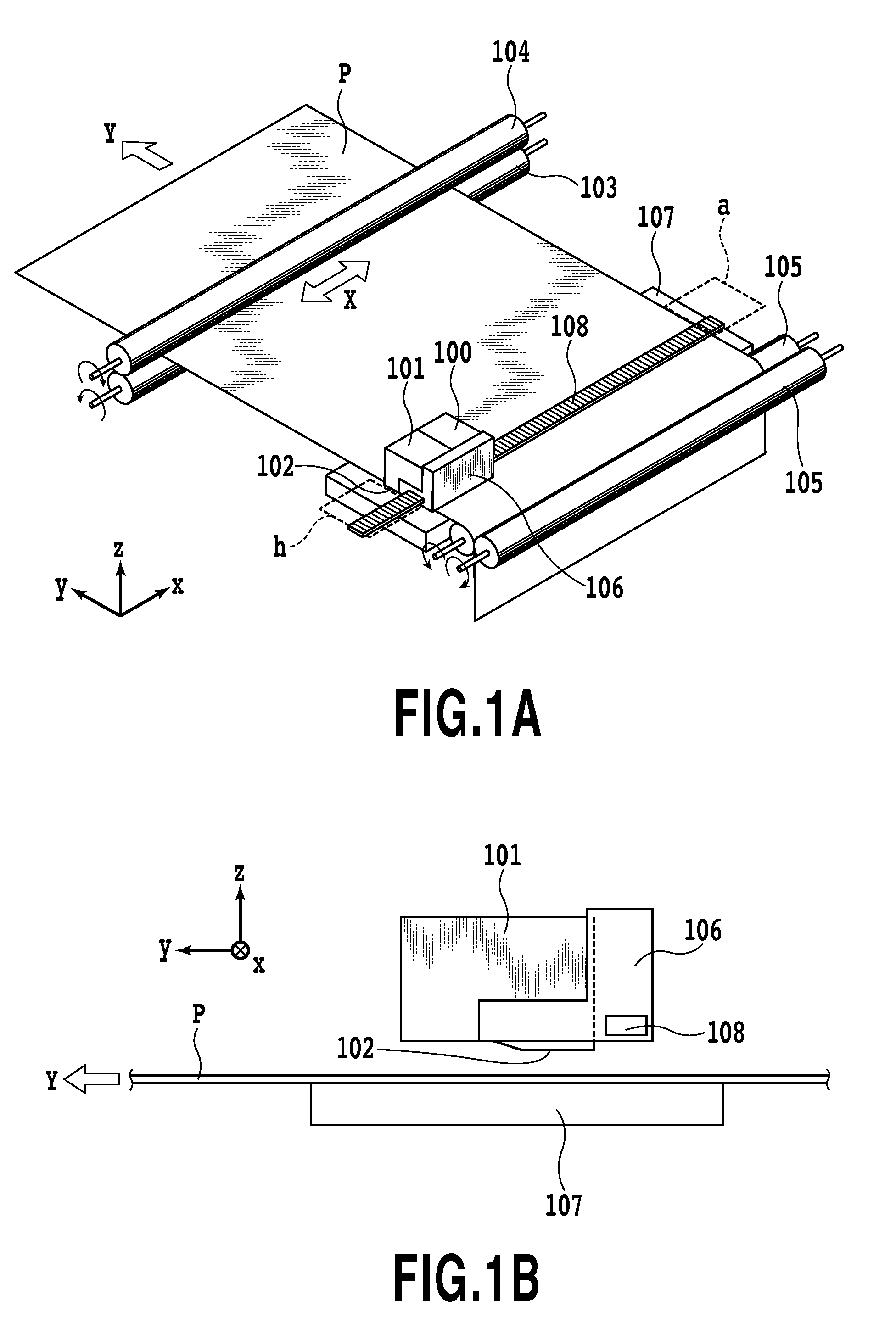
[0048]FIG. 1A is a schematic perspective view of an inkjet printing apparatus, and FIG. 1B is a side view of a print head portion of the inkjet printing apparatus.

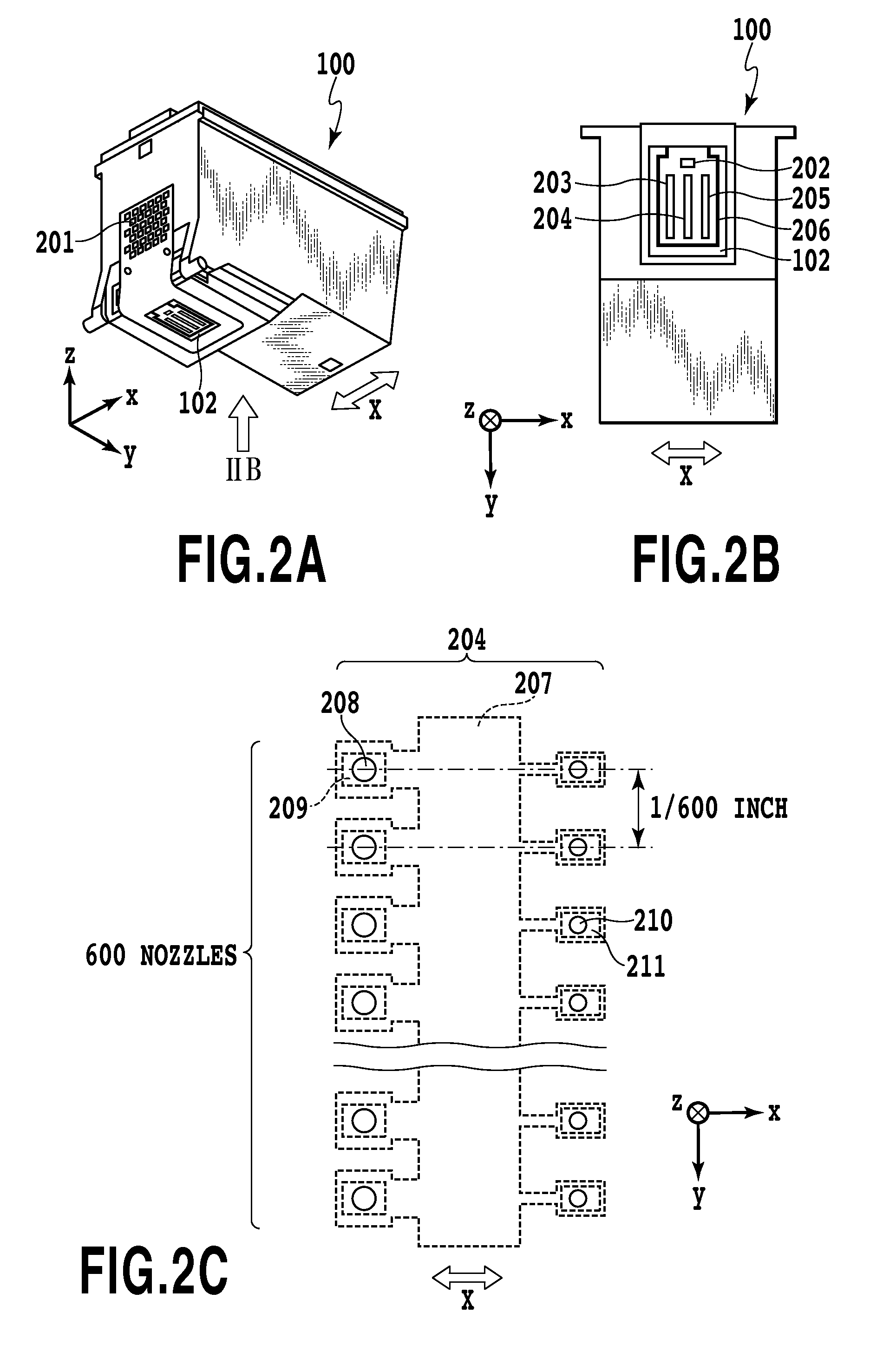
[0049]Each of inkjet print heads 100 and 101 constitutes an inkjet cartridge with which ink tanks are packaged. It should be noted, however, that the print heads are not limited to the type with which ink tanks are packaged, as in this embodiment. Three ink colors, i.e., black, light cyan and light magenta, are stored in the ink tanks provided for the print head 100, while three other ink colors, i.e., cyan, magenta and yellow, are stored in the ink tanks provided for the print head 101. The same structure is employed for both print heads 100 and 101, and only the ink stored in the ink tanks provided for the two print heads differs. The print heads 100 and 101 include head chips 102 wherein a plurality of ink ejection ports are arranged.

[0050]A conveying roller 103 and an auxiliary roller 104 hold a printing medium P and r...

second embodiment

[0085]In the first embodiment, printing is performed only by ejecting 5-pl ink droplets. In this embodiment, either a print mode (hereinafter also referred to as a “first print mode”) for ejecting only 5-pl ink droplets to print images, or a print mode (hereinafter also referred to as a “second print mode”) for ejecting only 2-pl ink droplets to print images is selected. In the first print mode, only ejection ports 208 for ejecting 5-pl ink are employed, and in the second print mode, only ejection ports 210 for ejecting 2-pl ink are employed. Images printed in this embodiment are the same as those in FIGS. 4A and 4B, previously described for the first embodiment.

[0086]FIG. 12 is a flowchart for explaining the print data generating process.

[0087]When a print data generating instruction is received, at S1201, a check is performed to determine whether the first or the second print mode has been selected. When the first print mode has been selected, the process is shifted to S1202, and ...

third embodiment

[0097]In the second embodiment, either the first print mode, for printing an image by ejecting ink of 5 pl, or the second print mode, for printing an image by ejecting ink of 2 pl, has been selected. In this embodiment, another print mode (hereinafter also referred to as a “third print mode”) for printing an image by ejecting ink of both 5 pl and 2 pl can also be selected. Images printed in this embodiment are the same as those in FIGS. 4A and 4B in the first and second embodiments.

[0098]FIG. 16 is a flowchart for explaining the print data generation processing.

[0099]When a print data generation instruction is received, at S1601 a check is performed to determine whether the first, the second or the third print mode is selected. When the first print mode is selected, the process is shifted to S1602, and the image signal processor 304 generates print data for ejecting 5-pl ink. When the second print mode is selected, the process is shifted to S1603, and the image signal processor 304 ...


PUM


Abstract

There are provided an inkjet printing apparatus and an inkjet printing method, whereby, the temperature of a print head is controlled and the ejection volume of ink to be ejected is stabilized to print a high-quality image, even at a high printing duty. Based on print data, an ejection number of ink to be ejected into a unit printing area is counted. The print head is heated to a target temperature that is raised in consonance with an increase in the count value.

Description

BACKGROUND OF THE INVENTION[0001]1. Field of the Invention[0002]The present invention relates to an inkjet printing apparatus and an inkjet printing method for printing an image on a printing medium by ejecting ink from an ejection opening of a print head on the basis of print data.[0003]2. Description of the Related Art[0004]The level of requests submitted for the performances of printing apparatuses, such as printers, copiers and facsimile machines, has been remarkably increased in recent years, and now, entries for such requests may include not only rapid and full color printing, but also high-definition printing providing the quality equivalent to that associated with silver halide film printing. Today, an ink ejection type printing apparatus (an inkjet printing apparatus) can comply with such a request because technology permits the formation, on an inkjet print head, of an array of nozzles for the high frequency ejection of tiny ink droplets, and can thus provide superior prin...

Claims


Application Information

Patent Timeline
Patent Type & Authority Applications(United States)
IPC IPC(8): B41J29/38
CPCB41J2/04528B41J2/0458B41J2/04563B41J2/04541
Inventor TANAKA, HIROKAZUKANDA, HIDEHIKOYAMAMOTO, WAKAKOOONUKI, KENICHI
Owner CANON KK
Learn More