Fenestration Segment Stent-Graft and Fenestration Method

a fenestration segment and stent technology, applied in the field of intravascular devices and methods, can solve the problems of affecting the treatment effect of patients, affecting the quality of life of patients, and affecting the quality of life of patients, and achieves the effect of reducing the risk of tearing

Inactive Publication Date: 2009-10-15
MEDTRONIC VASCULAR INC
View PDF43 Cites 88 Cited by
  • Summary
  • Abstract
  • Description
  • Claims
  • Application Information

AI Technical Summary

Benefits of technology

This patent describes a way to repair damaged blood vessels by putting a special type of stent graft called a fenestration segment stent-graft into place. This stent-graft protects a new branch vessel that comes off an existing main vessel. It's designed to be more resistant to torn compared to other parts of the stent-graft, which makes it easier for a healthcare professional to create a connection between the two branches without causing any damage during the process.

Problems solved by technology

The technical problem addressed by this patent is how to create a main stent-graft that can include custom side openings without requiring costly and time-consuming custom fabrication or causing temporary interruption of perfusion to branches vessels during placement.

Method used


Image

  • Fenestration Segment Stent-Graft and Fenestration Method
  • Fenestration Segment Stent-Graft and Fenestration Method
  • Fenestration Segment Stent-Graft and Fenestration Method

Examples


Embodiment Construction

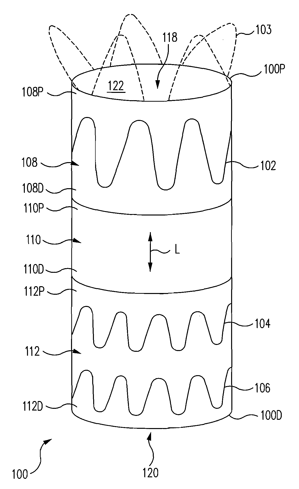
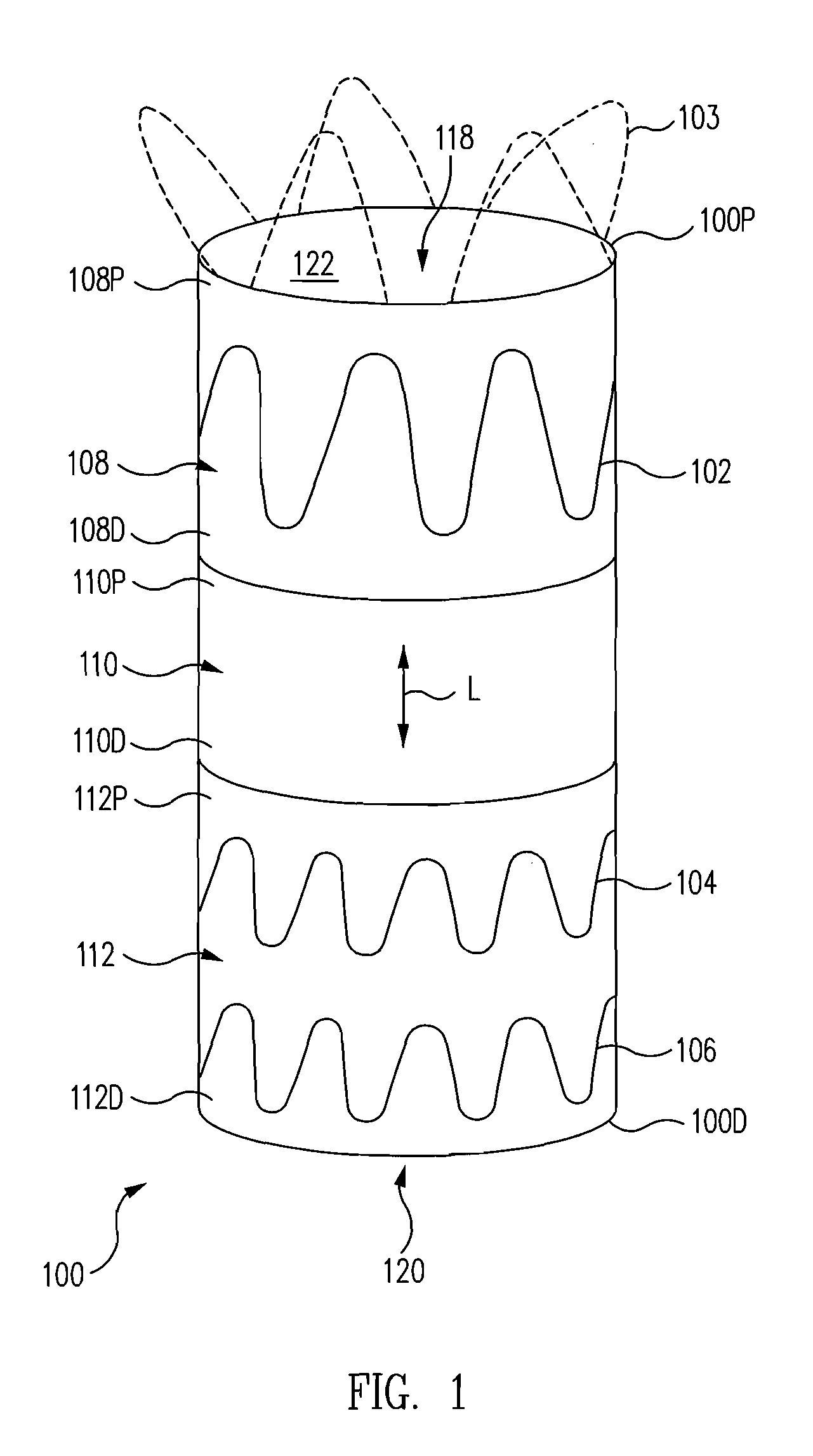
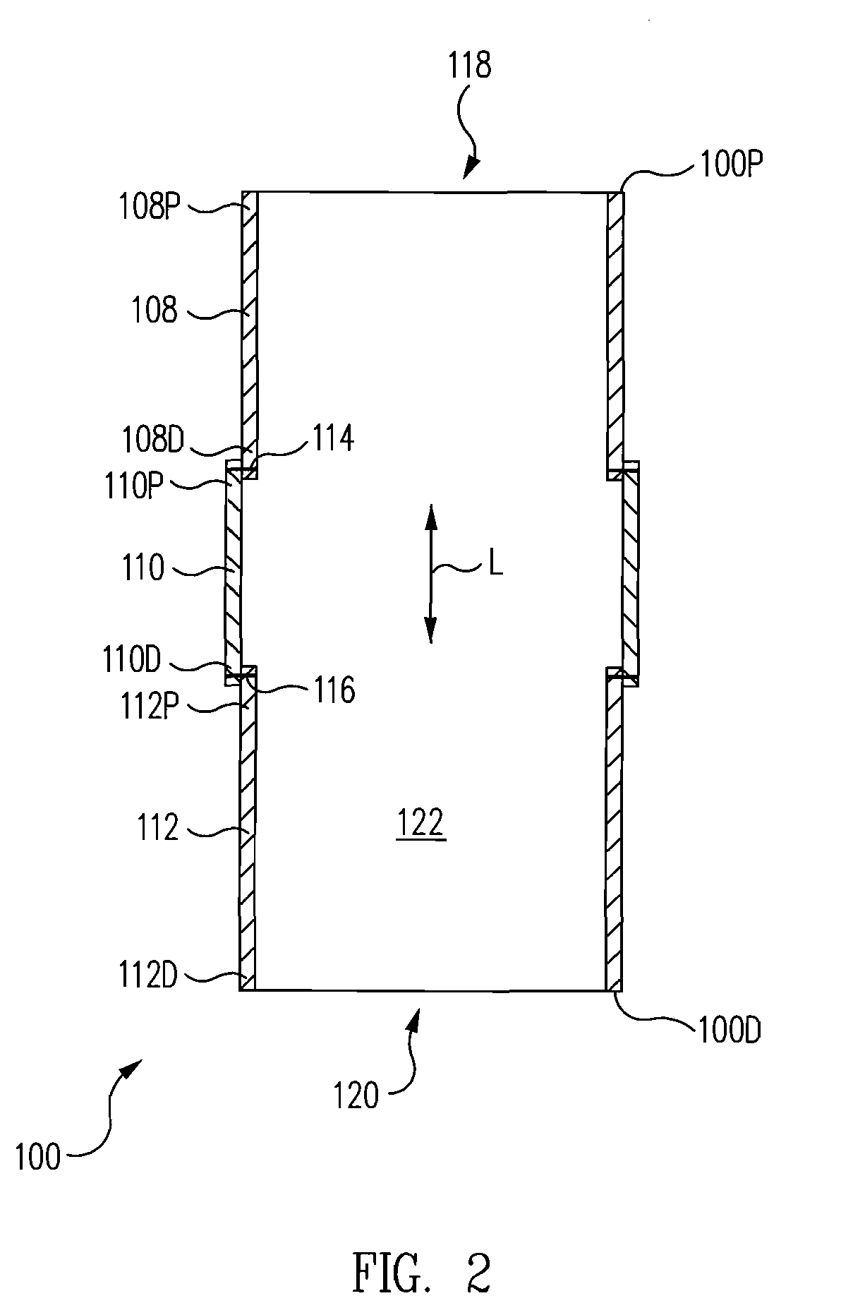
[0025]Referring to FIG. 8, a method includes deploying a fenestration segment stent-graft 100 into a main vessel 802 such that a fenestration section 110 of fenestration segment stent-graft 100 covers a first branch vessel 806 emanating from main vessel 802. Fenestration segment stent-graft 100 includes a proximal section 108, a distal section 112, and fenestration section 110 attached to and between proximal section 108 and distal section 112. Fenestration section 110 has a greater resistance to tearing than proximal section 108 and distal section 112 facilitating formation of a collateral opening 1112 (FIG. 16) aligned with branch vessel 806 in fenestration section 110.

[0026]In one example, fenestration section 110 is permeable thus allowing branch vessel 806 to be perfused through fenestration section 110. In this manner, branch vessel 806 is perfused through fenestration section 110 during the entire procedure of deploying and fenestrating fenestration segment stent-graft 100. A...


PUM


Abstract

A method includes deploying a fenestration segment stent-graft into a main vessel such that a fenestration section of the fenestration segment stent-graft covers a first branch vessel emanating from the main vessel. The fenestration segment stent-graft includes a proximal section, a distal section, and the fenestration section attached to and between the proximal section and the distal section. The fenestration section has a greater resistance to tearing than the proximal section and the distal section facilitating formation of a collateral opening aligned with the branch vessel in the fenestration section.

Description


Claims


Application Information

Patent Timeline
Owner MEDTRONIC VASCULAR INC
Why Eureka
Try Eureka