Tamper resistant hinge

Active Publication Date: 2009-10-22
IMPERIAL STAMPING CORP
View PDF18 Cites 2 Cited by
  • Summary
  • Abstract
  • Description
  • Claims
  • Application Information

AI Technical Summary

Benefits of technology

[0004]The present invention provides an anti-tamper member or plate that is fixedly attached to a hinge, such as the hinge of a bar lock system, in order to prevent access to the fasteners of the hinge when the bar lo

Problems solved by technology

However, the hinges to which the bar lock is pivotally mounted may have fasteners, such as screws or bolts, that are readily accessible

Method used


Image

  • Tamper resistant hinge
  • Tamper resistant hinge
  • Tamper resistant hinge

Examples


Embodiment Construction

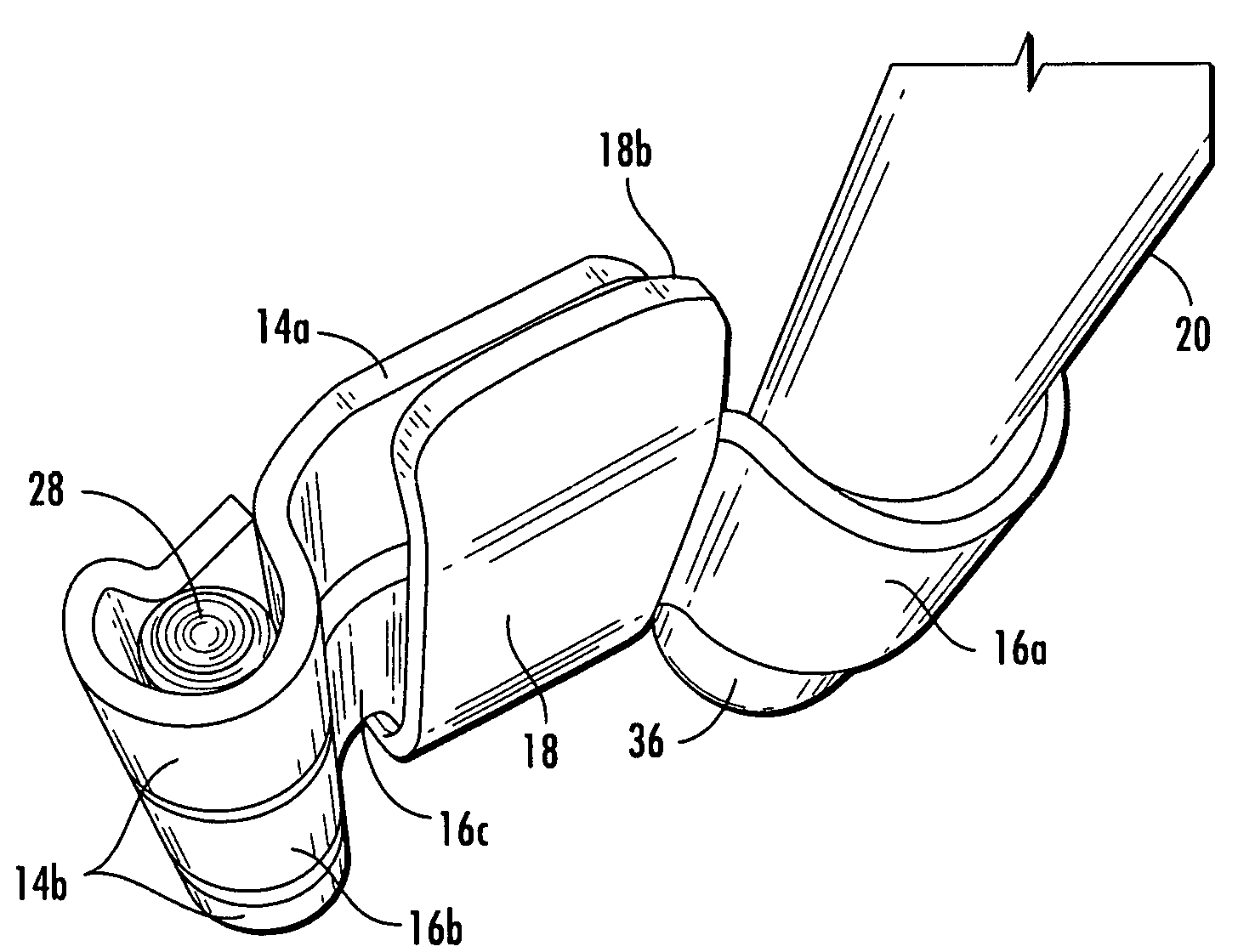
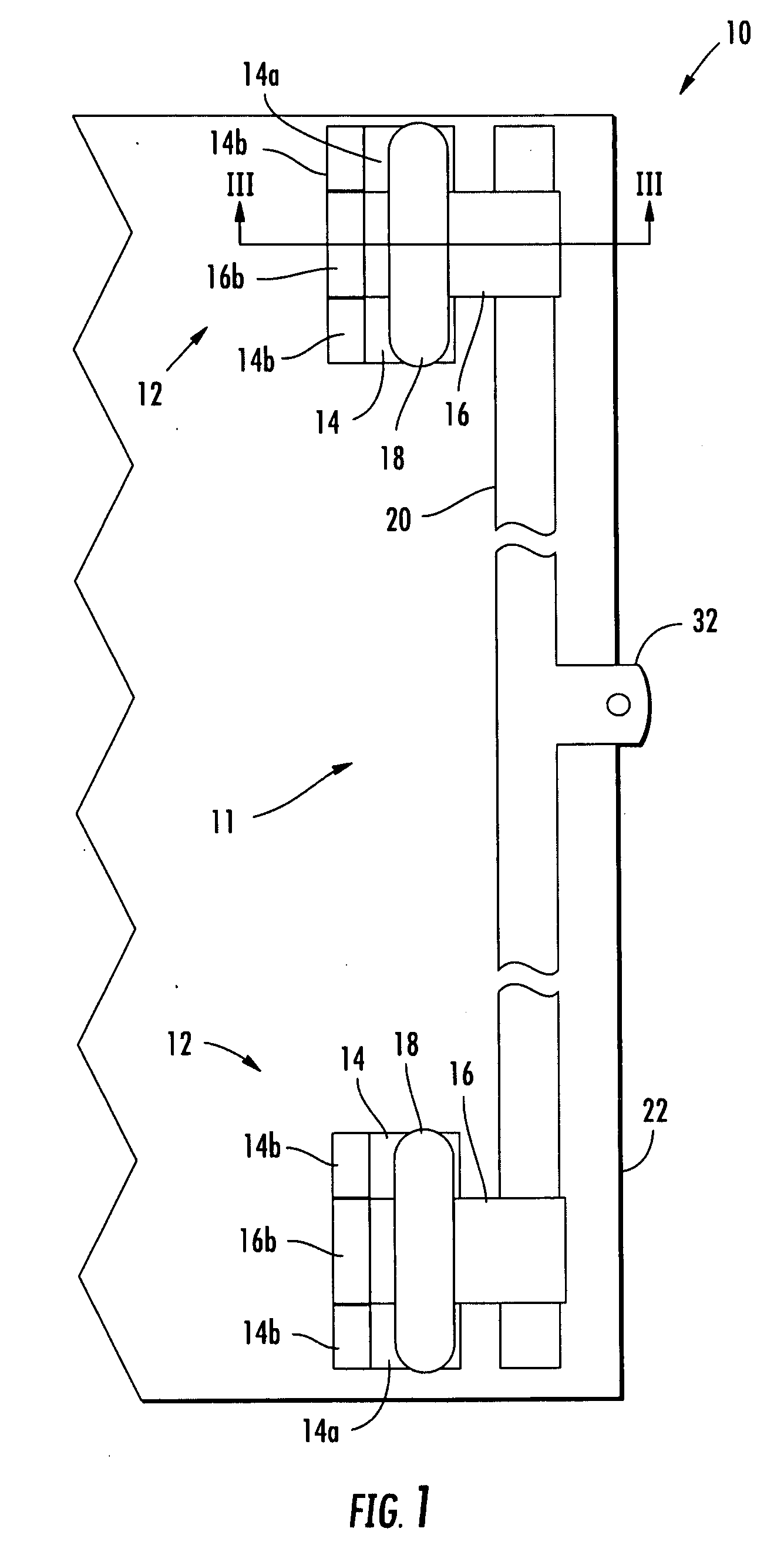
[0016]Referring now to the drawings and the illustrative embodiments depicted therein, a tamper resistant system 10 includes a bar lock assembly 11 and a pair of tamper resistant hinge assemblies 12 for securing an access door, such as a trailer or container door or the like. As will be more fully described below, each hinge assembly 12 substantially limits or prevents access to fasteners that hold bar lock assembly 11 to the access door or other mounting surface.

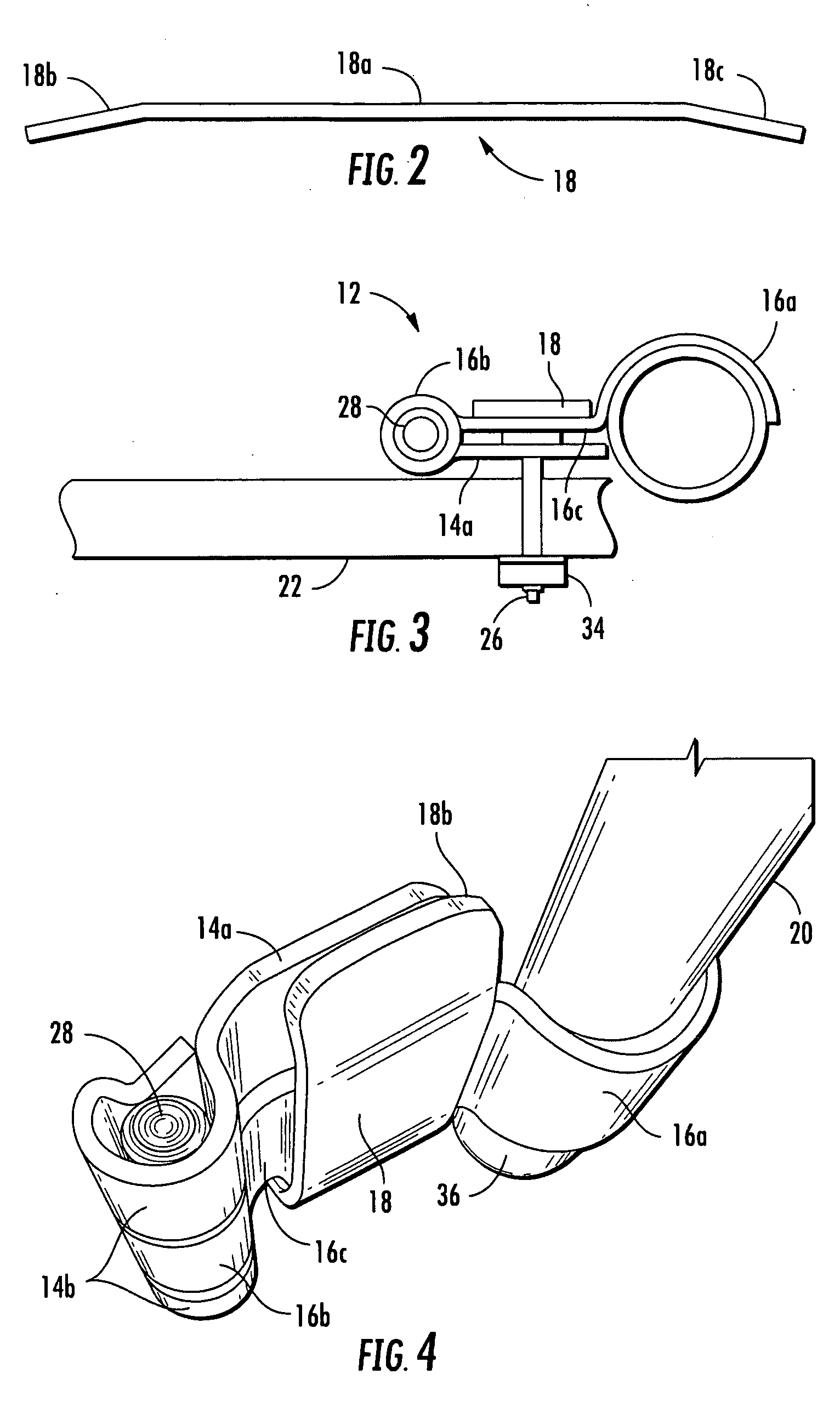
[0017]Hinge assembly 12 includes a hinge plate 14, a pivot member 16, and an anti-tamper member 18 (FIGS. 1 and 3-6). Hinge assemblies 12 are coupled together by a lock bar 20 that spans between hinge assemblies 12, which are connected to a mounting surface such as a door 22. Pivot member 16 is pivotally connected to hinge assembly 12 so that lock bar 20 may be moved or pivoted relative to hinge plate 14 and the mounting surface 22.

[0018]Hinge plate 14 includes a generally planar portion 14a that is positioned at or near do...


PUM


Abstract

A hinge assembly incorporates an anti-tamper member that is selectively positionable to protect fasteners holding the hinge assembly to a mounting surface such as an access door. The hinge assembly may be incorporated into a bar lock assembly to provide additional tamper resistance for a shipping container, for example, to limit or prevent unauthorized access to the container.

Description

CROSS REFERENCE TO RELATED APPLICATION[0001]The present application claims the benefit of U.S. provisional application Ser. No. 61 / 046,997, filed Apr. 22, 2008, which is hereby incorporated herein by reference in its entirety.FIELD OF THE INVENTION[0002]The present invention relates generally to hinges and, more particularly, to hinges used on container doors and the like.BACKGROUND OF THE INVENTION[0003]Access doors for containers, such as shipping containers, semitrailers, and the like, are typically hinged at one side and secured via a bar lock. The bar lock is typically pivotally mounted opposite the door hinges and is positionable between an open or unlocked position, and a closed or locked position. In the locked position, the bar lock is typically held in position by a shackle, a seal, a padlock, or the like. However, the hinges to which the bar lock is pivotally mounted may have fasteners, such as screws or bolts, that are readily accessible and / or removable, such that the b...

Claims


Application Information

Patent Timeline
IPC IPC(8): E05D11/00
CPCE05B83/10E05D11/0018E05Y2900/132Y10T16/533Y10T16/558Y10T16/5595Y10T16/5335
Inventor CONNER, PATRICK A.CHIDISTER, ROBERT I.
Owner IMPERIAL STAMPING CORP
Why Eureka
Try Eureka