Method of manufacturing coil assembly

a technology of rotary electric machines and coil wires, which is applied in the manufacture of stator/rotor bodies, magnets, magnetic bodies, etc., can solve the problems of increasing the number of man-hours and the risk of damage to the insulating film covering the surface of each coil wire segmen

Active Publication Date: 2009-10-22
DENSO CORP
View PDF30 Cites 21 Cited by
  • Summary
  • Abstract
  • Description
  • Claims
  • Application Information

AI Technical Summary

Benefits of technology

[0009]To achieve the above object, a first aspect of the present invention provides a method of manufacturing a coil assembly of a rotary electric machine, comprising: a preparing step for preparing first and second coil wire segments each having a plurality of turn portions; a locating step for locating the first and second coil wire segments on an axis direction in opposition to each other such that a first turn portion of the first coil wire segment and a first turn portion of the second coil wire segment intersect with each other; a first engaging step for conducting an engaging movement, composed of a forward transferring movement to transfer the second coil wire segment forward to the first coil wire segment, a rotating movement to rotate the second coil wire segment about the axis direction, and a translating movement to translate the second coil wire segment, for causing the first turn portion of either one of the first and second coil wire segments to engage a second turn portion of the other one of the first and second coil wire segments; and a second engaging step for conducting the engaging movement to allow the first turn portion of the either one of the first and second coil wire segments to engage a third turn portion of the other one of the first and second coil wire segments; whereby the first and second coil wire segments are woven to form the coil assembly.
[0010]With the manufacturing method mentioned above, the first and second coil wire segments are located in opposition to each other on the axis direction so as to cause the first turn portion of the first coil wire segment and the first turn portion of the second coil wire segment to intersect with each other. Thereafter, the first and second engaging steps are conducted in sequence to weave the first and second coil wire segments with each other.
[0011]In the first engaging step, conducting the engaging movement, composed of the forward transferring movement, the rotating movement and the translating movement, allows the first turn portion of either one of the first and second coil wire segments to engage a second turn portion of the other one of the first and second coil wire segments. In this case, during the translating movement of the engaging movement, the first and second coil wire segments are caused to engage with each other in different engaging patterns depending on a direction in which the second coil wire segment is transferred

Problems solved by technology

Therefore, an issue arises with the occurrence of an increase in the number of man-hours required and there is a risk of

Method used


Image

  • Method of manufacturing coil assembly
  • Method of manufacturing coil assembly
  • Method of manufacturing coil assembly

Examples


first embodiment

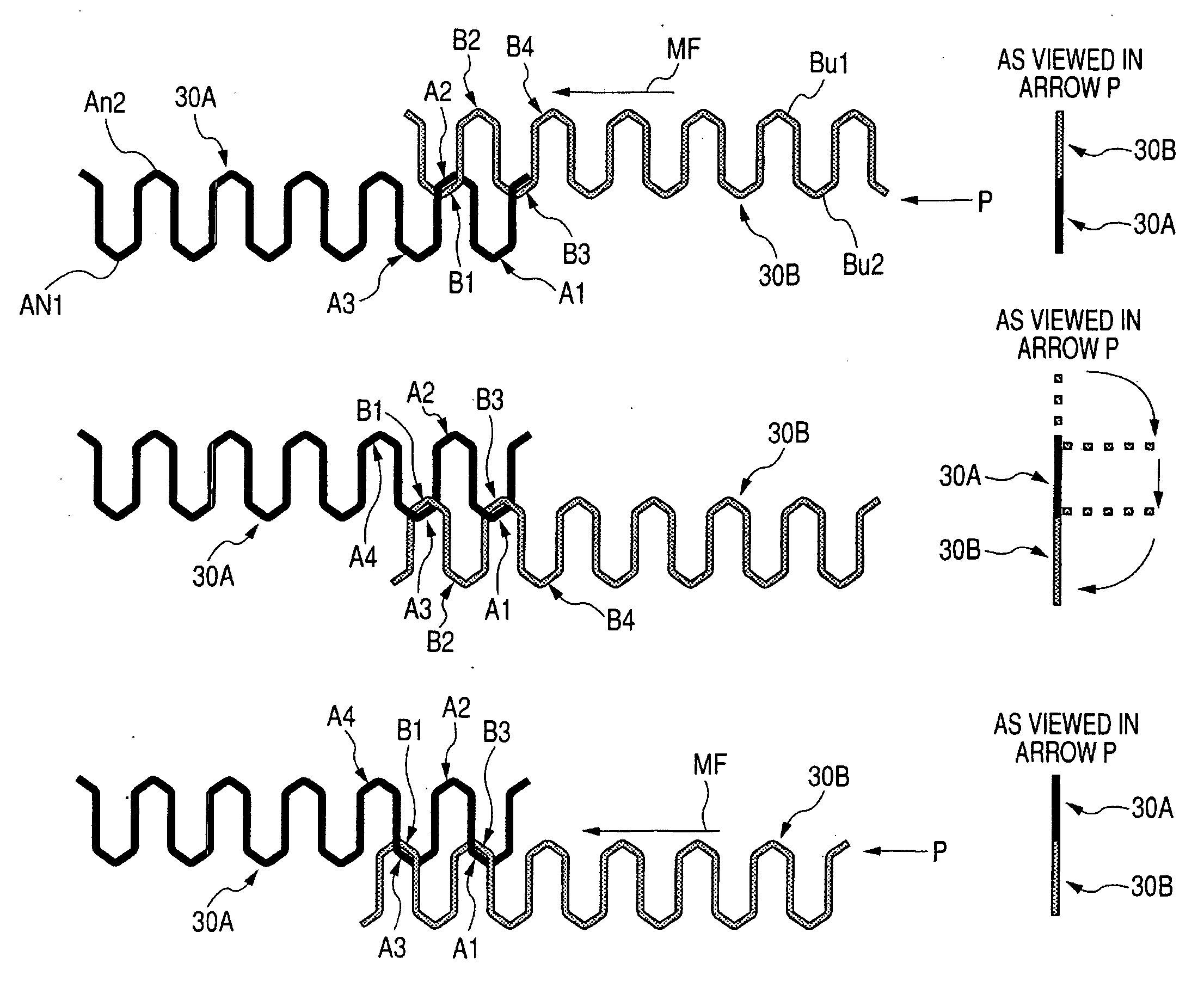
[0067]Next, a method of manufacturing the coil assembly 20 of a first embodiment will be described below in detail with reference to FIGS. 8A-8C and 9A-9C.

[0068]FIGS. 8A-8C and FIGS. 9A-9C are views illustrating how the coil wire segments are woven using a weaving method employed in the method of manufacturing the coil assembly 20 of the present embodiment. In FIGS. 8A-8C and FIGS. 9A-9C, right-hand views show first and second coil wire segments remained under woven states as view in arrows P.

[0069]With the first embodiment, first and second coil wire segments 30A and 30B are used each of which is preliminarily processed by forming linear shaped wire segments with the use of a pressing die and has the same shape as the coil wire segment 30 shown in FIG. 5. Moreover, it will be appreciated that the first and second coil wire segments 30A and 30B have turn portions similar in shape to those shown in FIG. 7 but simply illustrated in linear shapes in FIGS. 8A-8C and 9A-9C, respectively....

second embodiment

[0094]Next, a method of manufacturing a coil assembly 20A of a second embodiment will be described below with reference to FIGS. 10A to 10C and FIGS. 11A to 11D.

[0095]FIGS. 10A to 10C and FIGS. 11A to 11D are views illustrating how a weaving method is carried out to manufacture the coil assembly 20A of the present embodiment. In FIGS. 10A to 10C and FIGS. 11A to 11D, right-hand views show first and second coil wire segments remained under woven states as view in arrows P, respectively.

[0096]Hereunder, description is made of the weaving method for weaving coil wire segments with reference to FIGS. 10A to 10C and FIGS. 11A to 11D.

[0097]The first and second coil wire segments 30A and 30B, used in the second embodiment, have the same structures as those used in the first embodiment. In FIGS. 10A to 10C and FIGS. 11A to 11D, the respective turn portions, each formed in the stepwise shapes, of the first and second coil wire segments 30A and 30B are simply illustrated in linear shapes.

[009...


PUM

PropertyMeasurementUnit
Angleaaaaaaaaaa

Abstract

A method of manufacturing a coil assembly of a rotary electric machine is disclosed wherein first and second coil wire segments are located on an axis direction in opposition to each other to allow first turn portions of the first and second coil wire segments to intersect with each other (in locating step). Engaging movement, composed of a forward transferring movement, a rotating movement and a translating movement, is conducted on the second coil wire segment with respect to the first coil wire segment to allow the first turn portion of the second coil wire segment to engage a second turn portion of the first coil wire segment (first engaging step). Conducting the engaging movement allows to engage a third turn portion of the first coil wire segment (second engaging step).

Description

CROSS REFERENCE TO RELATED APPLICATIONS[0001]This application is based on Japanese Patent Application No. 2008-109594, filed on Apr. 18, 2008, the content of which is hereby incorporated by reference.BACKGROUND OF THE INVENTION[0002]1. Technical Field of the Invention[0003]The present invention relates to a method of manufacturing a coil assembly of a rotary electric machine.[0004]2. Description of the Related Art[0005]In the related arts, various methods have heretofore been proposed as a method of manufacturing a coil assembly of a rotary electric machine. For instance, Japanese Patent Application Publication 2002-176752 (Patent Publication 1) proposes a method in which a plurality of coil wire segments is simultaneously woven using a pair of plate-like winding cores placed in opposition to each other. Japanese Patent Application Publication 2004-104841 (Patent Publication 1) proposes a method of weaving coil wire segments into a coil assembly. The weaving method includes: a prepa...

Claims


Application Information

Patent Timeline
IPC IPC(8): H02K15/04H02K3/12
CPCH02K3/12H02K15/0478Y10T29/49009Y10T29/49071Y10T29/49012
Inventor KAMAKURA, YOUICHIGOROHATA, TETSUYAISHIZUKA, ATSUO
Owner DENSO CORP
Why Eureka
Try Eureka