Foldable hand tool

Inactive Publication Date: 2009-10-22
LAI CHIN TSAI
View PDF0 Cites 12 Cited by
  • Summary
  • Abstract
  • Description
  • Claims
  • Application Information

AI Technical Summary

Benefits of technology

[0007]The main objective of the present invention is to provide an improved

Problems solved by technology

However, the conventional hand tool still has some defects and needs to be advantageously altered.
The conventional hand tool can not exchange or replace the working element when being broken such that the user shoul

Method used


Image

  • Foldable hand tool
  • Foldable hand tool
  • Foldable hand tool

Examples


Embodiment Construction

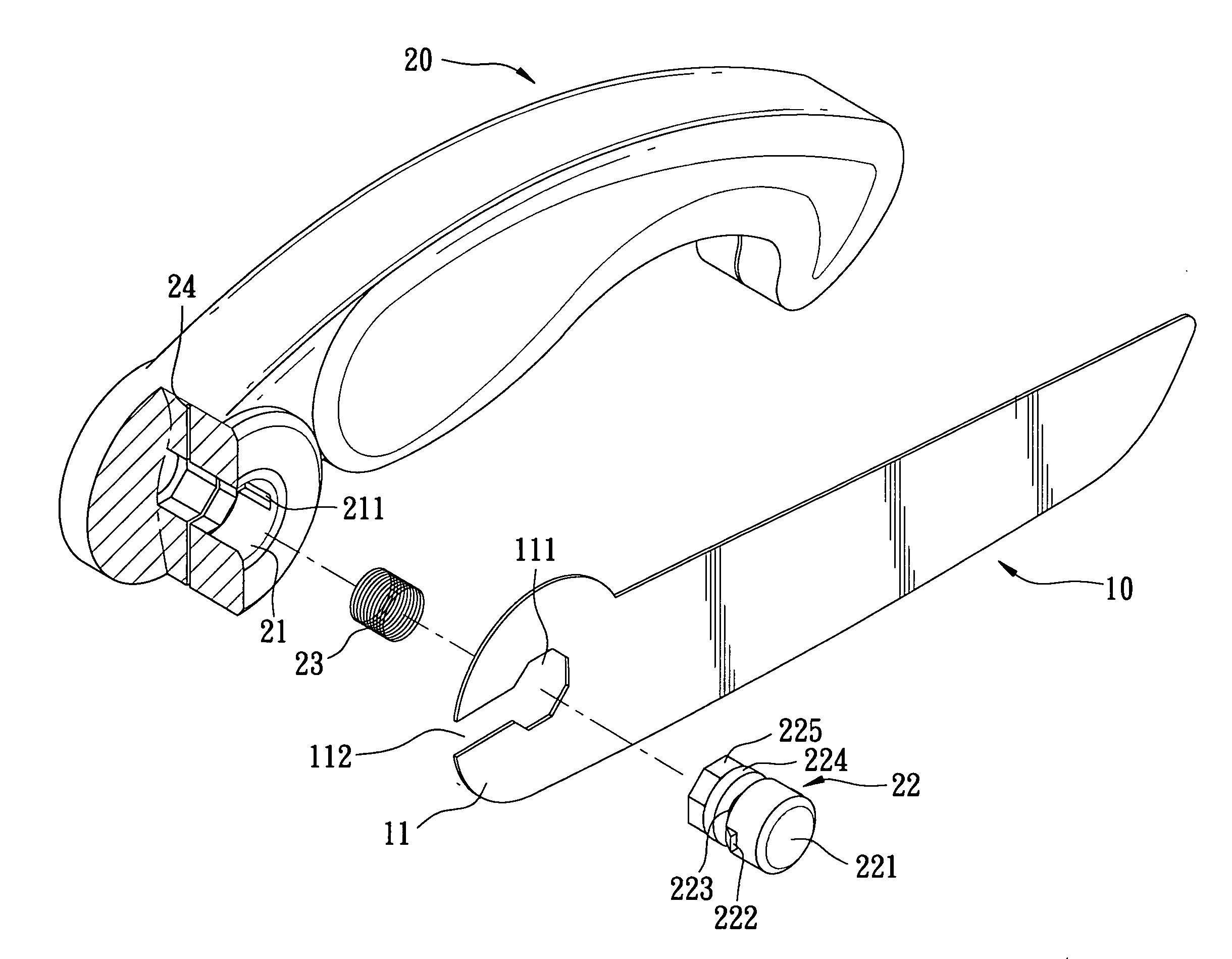
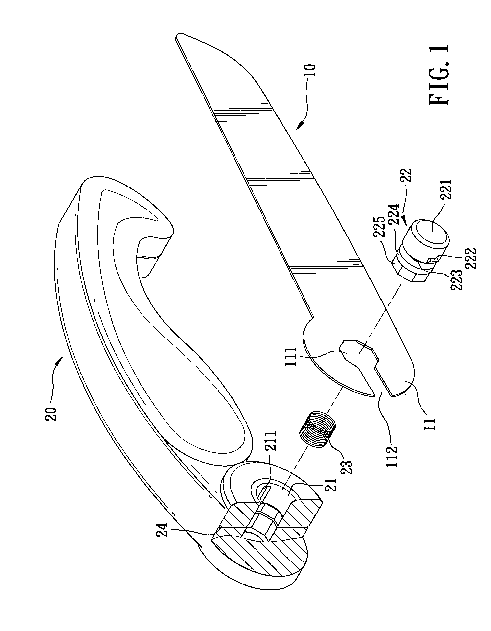
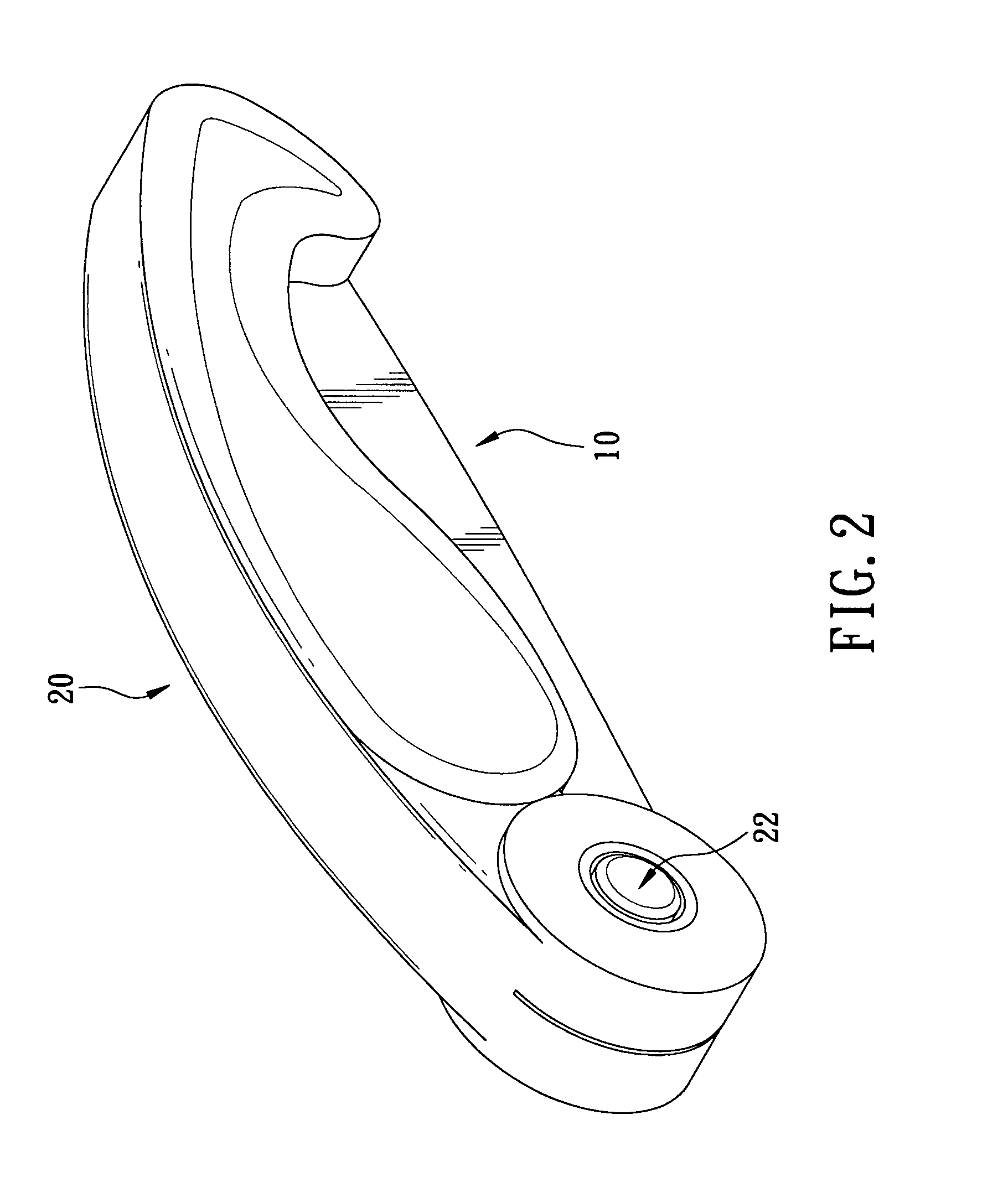
[0017]Referring to the drawings and initially to FIGS. 1-2, a foldable hand tool in accordance with the present invention comprises a handle (20), a working element (10) pivotally detachably connected to a front end of the handle (20) and a locking element (22) movably mounted in the front end of the handle (20) for selectively positioning the working element (10).

[0018]The handle (20) has a hole (21) laterally defined in the front end thereof. A slot (24) is defined in the front end of the handle (20) along an axis of the handle (20) and communicating with the hole (21). At least one rut (211) is longitudinally defined in an inner periphery of the hole (21). In the preferred embodiment of the present invention, there are two ruts (211) longitudinally defined in the inner periphery of the hole (21) and diametrically corresponding to each other.

[0019]With reference to FIGS. 1 and 6, the working element (10) has a pivotal end (11) pivotally received in the slot (24) in the front end o...


PUM

PropertyMeasurementUnit
Forceaaaaaaaaaa
Diameteraaaaaaaaaa
Elasticityaaaaaaaaaa

Abstract

A foldable hand tool includes a handle having a hole laterally defined in a font end of the handle for pivotally connecting to a working element. The working element has a pivotal end pivotally received in the front end and a polygonal hole which is centrally defined in the pivotal end. A groove is radially defined in the pivotal end and communicates with the polygonal hole. A locking element is reciprocally movably mounted in the hole in the handle for selectively positioning the working element.

Description

BACKGROUND OF THE INVENTION[0001]1. Field of the Invention[0002]The present invention relates to a foldable hand tool, and more particularly to a foldable hand tool that has a replaceable and adjustable working element for different work types.[0003]2. Description of Related Art[0004]A conventional hand tool in accordance with the prior art comprises a handle having a slot defined in a front end of the handle along with a axis of the handle for selectively receiving a working element, wherein the working element is pivotally connected to the front end of the handle and received in the slot when the conventional hand tool is folded.[0005]The conventional hand tool is foldable for being carried easily. However, the conventional hand tool still has some defects and needs to be advantageously altered. The conventional hand tool can not exchange or replace the working element when being broken such that the user should prepare a lot of the hand tools in advance for contingent use. It cos...

Claims


Application Information

Patent Timeline
IPC IPC(8): B26B1/04
CPCB23D51/01B23D51/10B26B1/046B25G3/18B25G3/38B25G1/08
Inventor LAI, CHIN TSAI
Owner LAI CHIN TSAI
Why Eureka
Try Eureka