Image pickup unit that allows optical adjustment

a technology of optical adjustment and image pickup, which is applied in the field of image pickup units, can solve the problems of deteriorating image quality of image data obtained, work to loosen the adjusting screws, and the image pickup surface of an image sensor like a cmos sensor may tilt, so as to simplify the optical adjustment work

Active Publication Date: 2020-04-16
CANON KK
View PDF0 Cites 2 Cited by
  • Summary
  • Abstract
  • Description
  • Claims
  • Application Information

AI Technical Summary

Benefits of technology

[0007]The present invention provides an image pickup unit that is capable of simplifying an optical adjustment work for an image pickup surface.
[0009]According to the present invention, the optical adjustment work for the image pickup surface is simplified.

Problems solved by technology

Moreover, an image pickup surface of an image sensor like a CMOS sensor may tilt with respect to a plane that intersects perpendicularly with a design optical axis due to a manufacture error.
If there is tilt deviation between an image plane of an optical system and an image pickup surface of an image sensor due to the tilts of the image plane and the image pickup surface, image quality of the image data obtained will deteriorate.
Accordingly, the work to loosen the adjusting screws is always required, even when a manufacture error is small.
Accordingly, there is a problem that the optical adjustment work of an image pickup surface is not easy.
However, since this design eliminates the adjustment margin for the tilt adjustment that tilts the holding plate toward the lens barrel, the adjustable range of the tilt adjustment becomes narrow.

Method used


Image

  • Image pickup unit that allows optical adjustment
  • Image pickup unit that allows optical adjustment
  • Image pickup unit that allows optical adjustment

Examples


Embodiment Construction

[0026]Hereafter, embodiments according to the present invention will be described in detail by referring to the drawings.

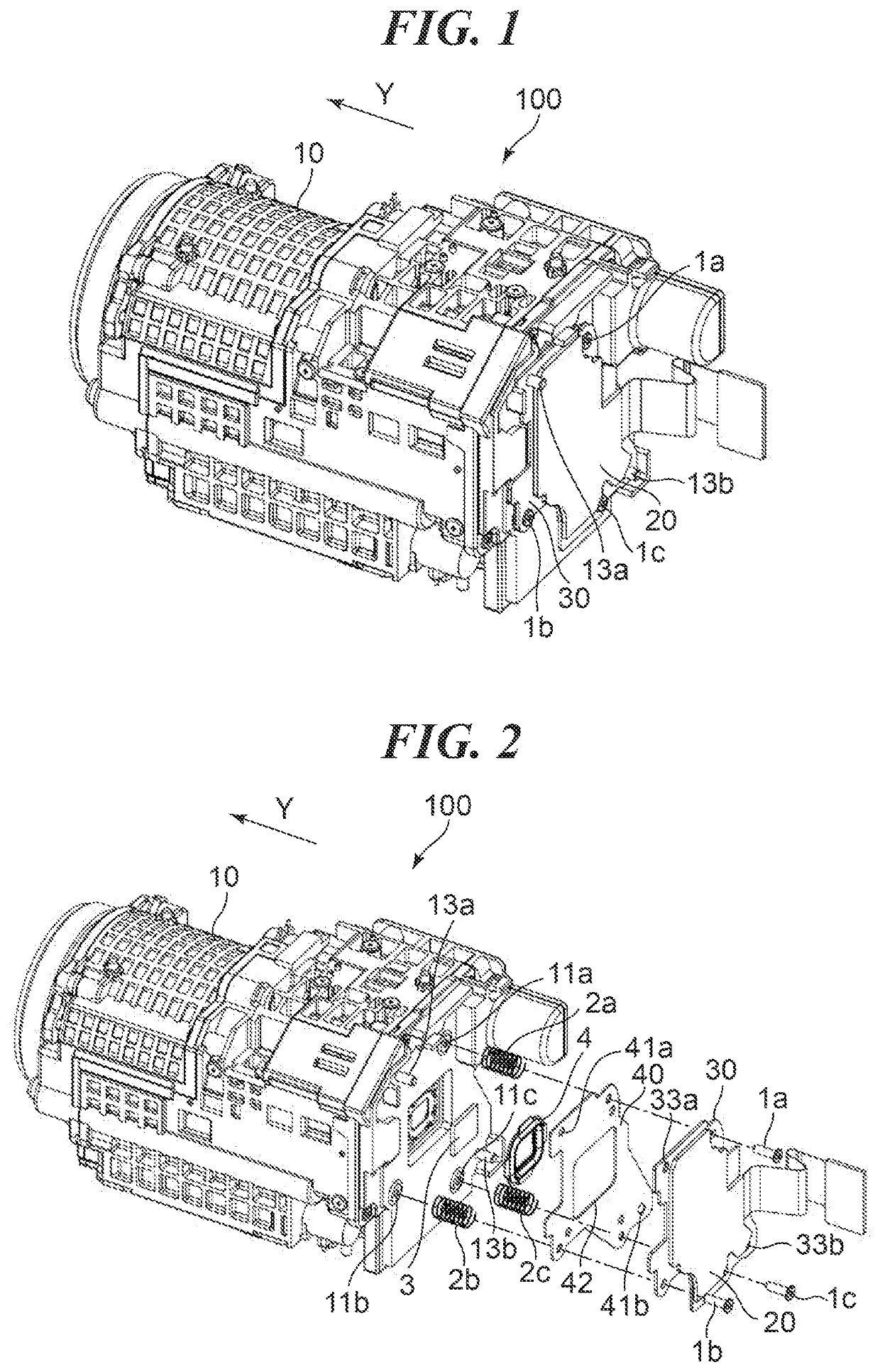
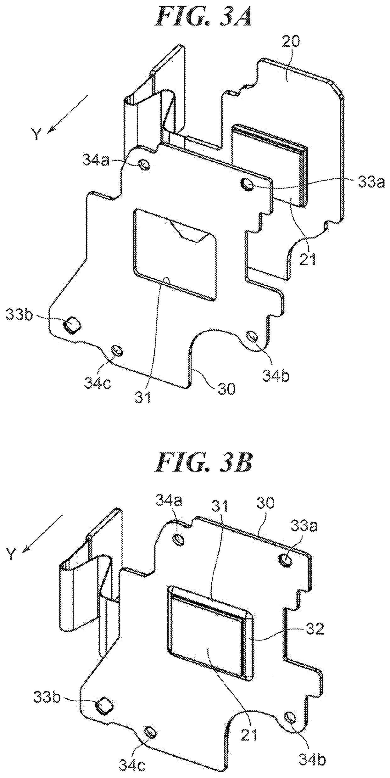
[0027]FIG. 1 and FIG. 2 are respectively a perspective view and an exploded perspective view showing an image pickup unit according to a first embodiment of the present invention. This image pickup unit 100 is applied to a video camera, for example. Hereinafter, an object side shall be a front side (+Y side in the drawings) and the opposite side (−Y side) shall be a back side.

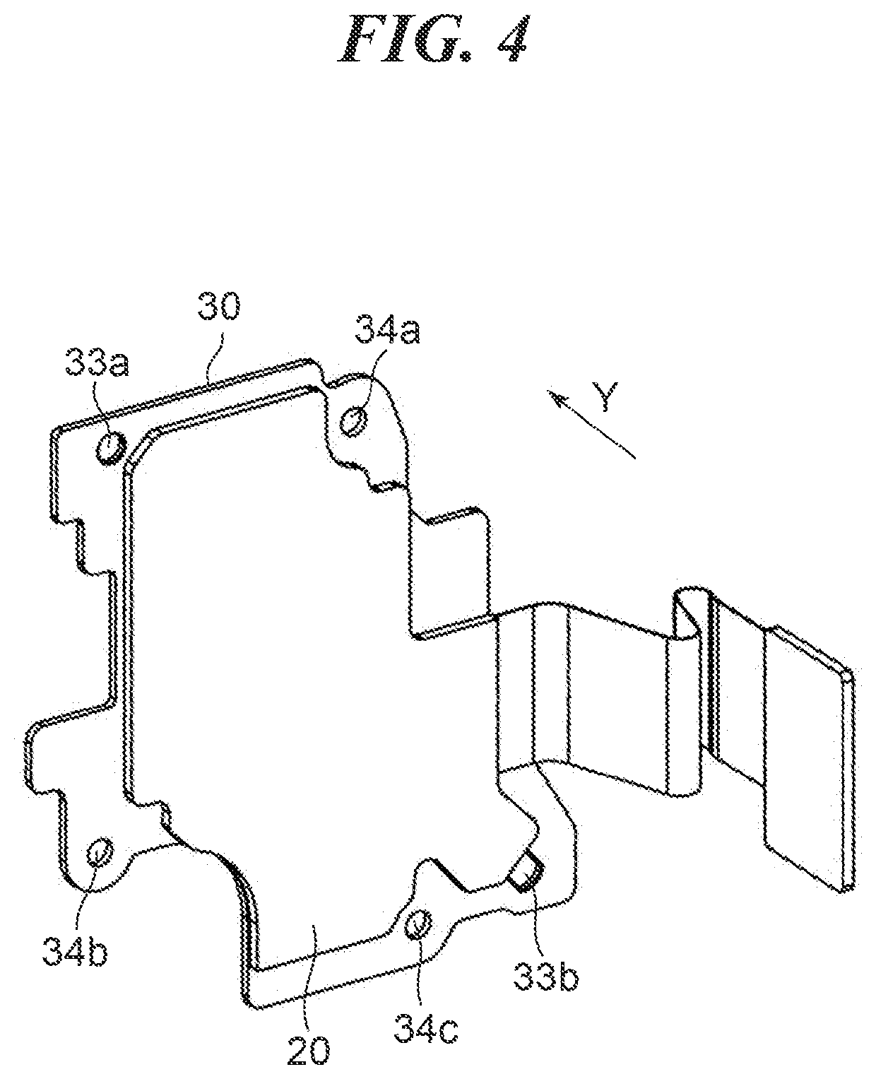
[0028]The image pickup unit 100 has a lens barrel 10, a sensor substrate 20, a holding plate 30, a shim plate 40, a first adjusting screw 1a, a second adjusting screw 1b, a third adjusting screw 1c, a first spring 2a, a second spring 2b, a third spring 2c, a glass 3, and an elastic member 4. An optical axis X (FIGS. 6B, 7A, and 7B) of an optical system built in the lens barrel 10 is parallel to a Y-direction in design. The optical axis X is an ideal design optical axis. A CMOS sensor 21 (FIG....


PUM


Abstract

An image pickup unit that is capable of simplifying an optical adjustment work for an image pickup surface. A holding plate holds an image sensor. A lens barrel includes an optical system that forms an object image on the image sensor. A removable shim plate is inserted between the lens barrel and the holding plate and has a shape to avoid the image sensor. An energizing mechanism is inserted between the shim plate and the lens barrel to energizes the shim plate and the holding plate in a direction away from the lens barrel. Three adjusting screws fix the holding plate and shim plate to the lens barrel. Each of the adjusting screws displaces corresponding portions of the shim plate and holding plate toward the lens barrel when being fastened and displaces the corresponding portions away from the lens barrel in cooperation with the energizing mechanism when being loosened.

Description

BACKGROUND OF THE INVENTIONField of the Invention[0001]The present invention relates to an image pickup unit that allows optical adjustment of an image pickup surface of an image sensor.Description of the Related Art[0002]Generally, an image pickup unit provided in a video camera etc. converts an optical image of an object formed by an optical system included in a lens barrel etc. into an electrical signal using an image sensor like a CMOS sensor. The converted electrical signal is converted into image data by an image processing IC, and is recorded on a memory etc.[0003]Since an optical system provided in a lens barrel may have a tilt or displacement of a lens or a lens holding member due to a manufacture error, an image plane of an optical system may tilt with respect to a plane that intersects perpendicularly with a design optical axis. Moreover, an image pickup surface of an image sensor like a CMOS sensor may tilt with respect to a plane that intersects perpendicularly with a d...

Claims


Application Information

Patent Timeline
Patent Type & Authority Applications(United States)
IPC IPC(8): H04N5/225G02B7/02
CPCG02B7/023H04N5/2253H04N5/2254H04N23/54H04N23/55
Inventor IFUKU, HIROTAKA
Owner CANON KK
Why Eureka
Try Eureka