Charged particle beam device

a charge-pulverized particle and beam technology, applied in the direction of beam deviation/focusing by electric/magnetic means, instruments, heat measurement, etc., can solve the problems of affecting the observation of an enlarged image during operation, and the slight misalignment of the beam, so as to save labor and time, and the cumbersome adjustment work can be restrained

Inactive Publication Date: 2009-09-03
HITACHI HIGH-TECH CORP
View PDF2 Cites 2 Cited by
  • Summary
  • Abstract
  • Description
  • Claims
  • Application Information

AI Technical Summary

Benefits of technology

[0016]According to the present invention, even if the anode position is changed, optical axis adjustment can be made automatically, which saves labor and time spent for the optical axis adjustment, and a cumbersome adjustment work can be restrained. Also, even at a low-acceleration voltage, observation can be made with a sufficient electron dose (brightness) required for image observation.

Problems solved by technology

In the electronic microscope, an optical axis of an electron beam generation portion (electron gun) is not matched with the optical axis with an irradiation lens system located on a rear stage due to the positional change of the anode, which causes a slight misalignment and affects observation of an enlarged image during operation.

Method used


Image

  • Charged particle beam device
  • Charged particle beam device
  • Charged particle beam device

Examples


Embodiment Construction

[0069]The present invention is not limited to the mode described in the description but allows improvements and changes of the invention. This embodiment will be described using an electronic microscope as an example, but the present invention may be applied to other devices such as an ion beam device, for example.

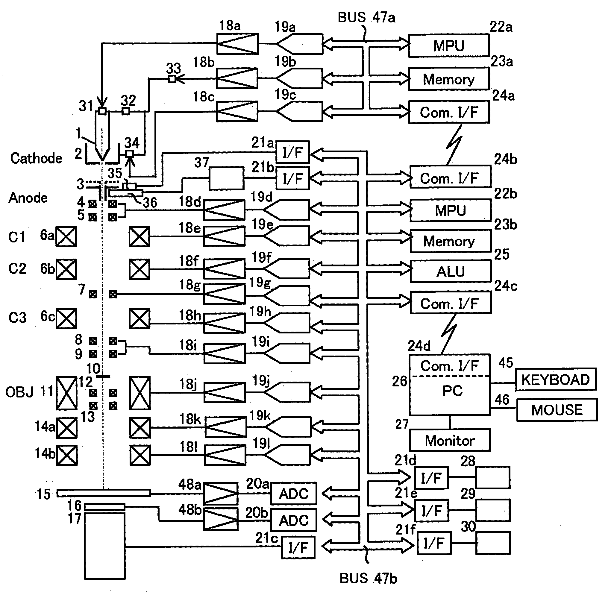
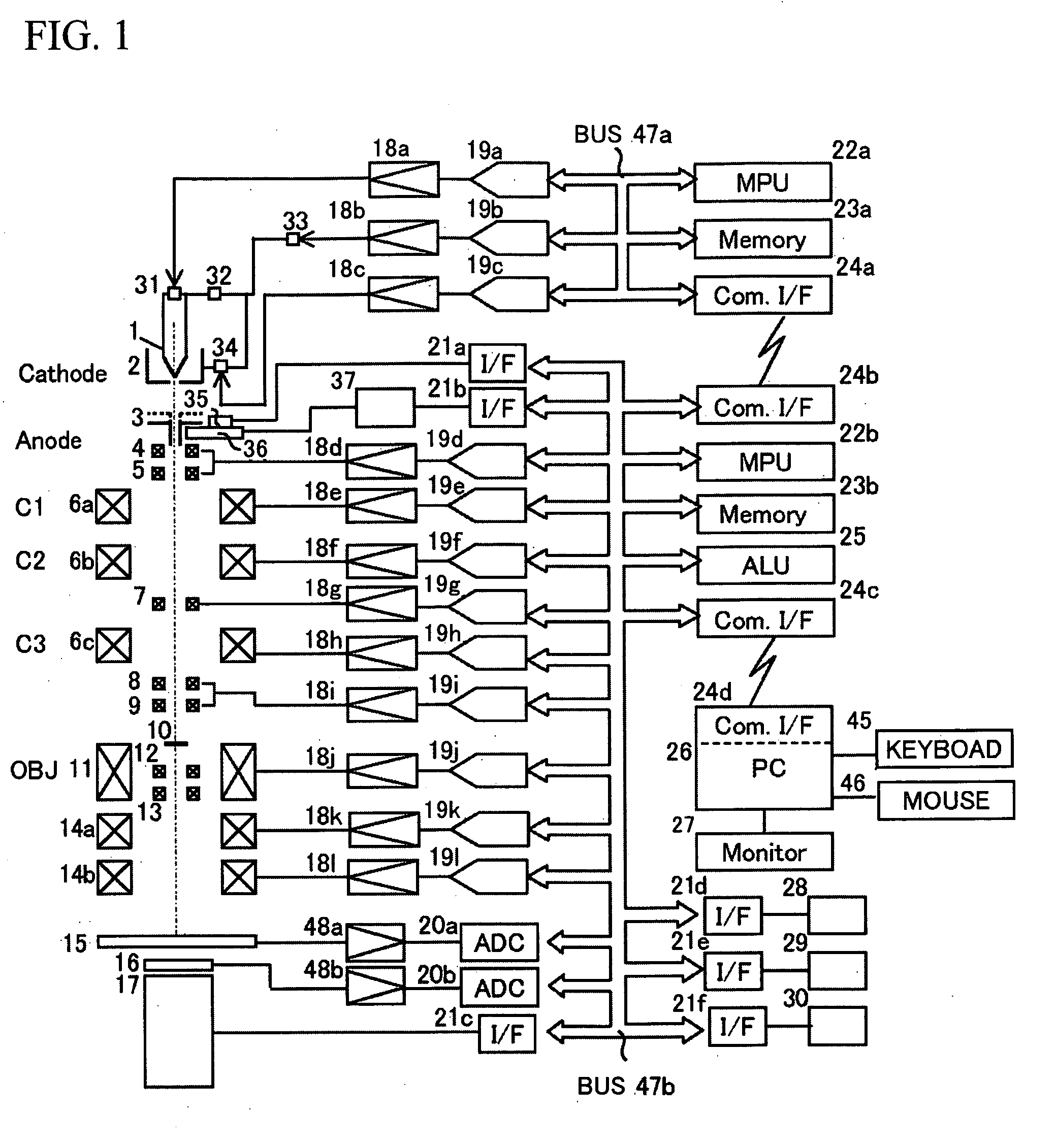
[0070]Specifically, there are provided a cathode provided with an electron source which emits an electron, an anode which applies an electric field to the emitted electron, an electron beam deflector which deflects an orbit of the electron beam having passed the anode, and an electron beam detector which detects the electron beam from a sample to which the electron is irradiated, and a distance changing mechanism which changes a distance between the cathode and the anode, corresponding to a change in a set voltage to be applied to the cathode and a deflection amount control mechanism which detects a deflection amount at which the electron dose detected from the sample scan...


PUM


Abstract

The present invention provides a charged particle beam device which can effectively restrain misalignment of an optical axis even if a position of an anode is changed. The present invention is a charged particle beam device comprising a cathode provided with a charged particle source which emits a charged particle, an anode which applies an electric field to the emitted charged particle, a charged particle beam deflector which deflects an orbit of a charged particle beam having passed the anode, and a charged particle beam detector which detects the charged particle beam from a sample to which the charged particle is irradiated, wherein a distance changing mechanism which changes a distance between the cathode and the anode, corresponding to a charged particle amount emitted from the charged particle source and a deflection amount control mechanism which detects a condition of the deflector under which the charged particle dose detected from the sample scanned by deflecting the charged particle beam in the changed distance becomes a desired size and controls deflection of the deflector at sample measurement on the basis of the condition are provided.

Description

BACKGROUND OF THE INVENTION[0001]1. Field of the Invention[0002]The present invention relates to a charged particle beam device.[0003]2. Background Art[0004]Usually, in a charged particle source peripheral mechanism of a charged particle beam device such as an electron gun of an electronic microscope, a distance between a cathode (negative electrode) and an anode (positive electrode) is fixed. Thus, if a low-acceleration voltage is applied in use, an electric field intensity lacks, and a sufficient electron dose can not be drawn out of the cathode. In order to improve this, as a mechanism that can vary a position of the anode, there is a related art (JP Utility Model Registration No. 1016333 (JP Utility Model Publication (Kokoku) No. 48-5947 Y (1973))) configured such that the above distance is shorten when a low-acceleration voltage is applied and a sufficient electron dose can be drawn out of the cathode by increasing the electric field intensity. Also, in JP Patent Publication (K...

Claims


Application Information

Patent Timeline
Patent Type & Authority Applications(United States)
IPC IPC(8): H01J3/14
CPCH01J37/1471H01J37/26H01J2237/2802H01J2237/065H01J2237/1501H01J2237/024
Inventor FUJISAWA, AKIKOKOBAYASHI, HIROYUKINAKAZAWA, EIKO
Owner HITACHI HIGH-TECH CORP
Why Eureka
Try Eureka