Optical displacement sensor and external force detecting device

a technology of optical displacement sensor and detecting device, which is applied in the direction of instruments, instruments, and instruments for force/torque/work measurement, etc., can solve the problems of affecting the accuracy of the measurement, the adjustment of the rotational angle about the z-axis perpendicular to the x- and y-axes is difficult, and the work is laborious, so as to reduce the time, the adjustment is easy, and the effect of reducing the tim

Active Publication Date: 2007-04-24
MINEBEAMITSUMI INC
View PDF6 Cites 2 Cited by
  • Summary
  • Abstract
  • Description
  • Claims
  • Application Information

AI Technical Summary

Benefits of technology

[0012]The present invention has been made in light of the above problem, and it is an object of the present invention to provide an optical displacement sensor, and an external force detecting device, in which a position of a light receiving means relative to a light source with respect to a rotational direction about an optical axis of light emitted from the light source can be adjusted easily in a reduced time.
[0019]According to a fifth aspect of the present invention, there is provided a method of adjusting such an optical displacement sensor as structured according to the first aspect of the present invention. The method comprises a step of adjusting a position of the light receiving means relative to the light source with respect to a rotational direction about the optical axis of the light emitted from the light source based on a reception state of the higher-order beams at the second light receiving element group. Consequently, the optical displacement sensor can be adjusted without troublesome work in a reduced time.
[0020]According to a sixth aspect of the present invention, there is provided a method of adjusting such an optical displacement sensor as structured according to the second aspect of the present invention. The method comprises a step of adjusting a position of the light receiving means relative to the light source with respect to a rotational direction about the optical axis of the light emitted from the light source based on a reception state of the light at the light receiving means. Consequently, the optical displacement sensor can be adjusted easily without provision of the light diffracting element and the second light receiving element group used in the first aspect.
[0021]According to a seventh aspect of the present invention, there is provided a method of adjusting such an optical displacement sensor as structured to the third aspect of the present invention. The method comprises a step of adjusting a position of the light receiving means relative to the light source with respect to a rotational direction about the optical axis of the light emitted from the light source based on a reception state of the higher-order beams at the second light receiving element group. Consequently, the optical displacement sensor structured to include the reflector member can be also adjusted without troublesome work in a reduced time.
[0022]According to an eighth aspect of the present invention, there is provide a method of adjusting such an optical displacement sensor as structured according to the fourth aspect of the present invention. The method comprises a step of adjusting a position of the light receiving means relative to the light source with respect to a rotational direction about the optical axis of the light emitted from the light source based on a reception state of the light at the light receiving means. Consequently, the optical displacement sensor provided with the reflector member can be adjusted easily without provision of the light diffracting element and the second light receiving element group used in the third aspect.
[0023]According to a ninth aspect of the present invention, an external force detecting device is provided which incorporates an optical displacement sensor structured according to any one of the aforementioned first to fourth aspects, and an external force applied to a measurement object is detected based on a signal containing a measurement result by the optical displacement sensor. In the ninth aspect of the present invention, the optical displacement sensor may be provided in a plural number, and a plurality of optical displacement sensors may detect respective displacements with respect to two-axis directions different from one another. Since the external force detecting device incorporates the optical displacement sensors according to the present invention, the adjustment work about the device can be performed easily in a reduced time.

Problems solved by technology

Specifically, in the alignment work, while positional adjustment with respect to the X- and Y-axis directions is easy, rotational adjustment about a Z-axis perpendicular to the X- and Y-axes (to precisely bring the cross-shaped boundary formed by the four PD's 108a in line with the X- and Y-axes) is very difficult
This involves a lot of works, and requires an immense amount of time and effort, especially when displacement amount is large.

Method used


Image

  • Optical displacement sensor and external force detecting device
  • Optical displacement sensor and external force detecting device
  • Optical displacement sensor and external force detecting device

Examples


first embodiment

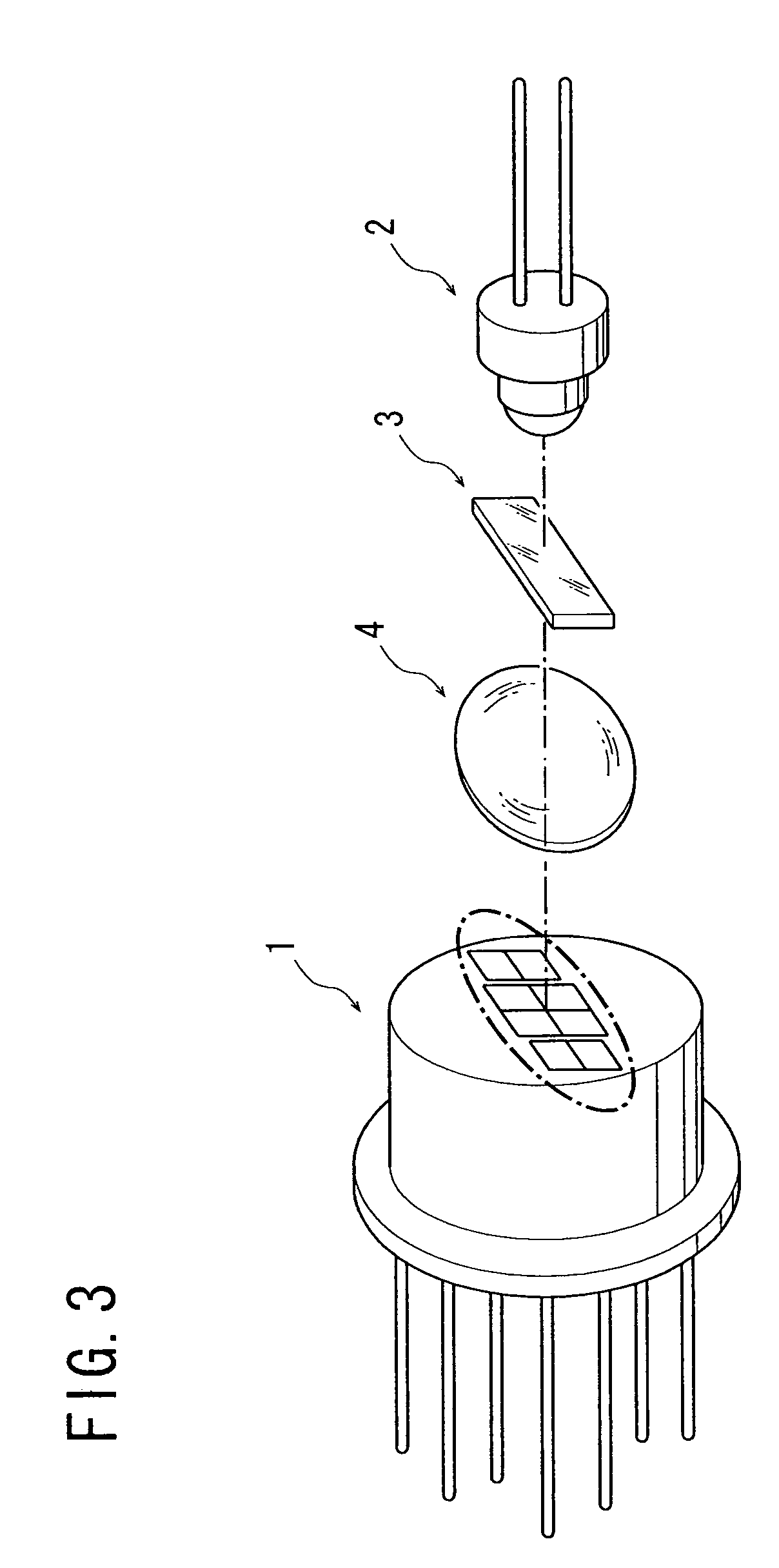
[0035]the present invention will be described with reference to FIGS. 3 to 6. Referring first to FIG. 3, an optical displacement sensor comprises: a photodiode (PD) assembly 1 as a light receiving means; a light emitting diode (LED) 2 which is a light emitting element as a light source; a light diffracting element 3 to disperse one beam into three beams; and a lens 4 to shape and condense beams.

[0036]In the optical displacement sensor shown in FIG. 3, the PD assembly 1 is mounted at one of a reference object and a measurement object, and the LED 2 is mounted at the other one thereof, at which the PD assembly 1 is not mounted, wherein light emitted from the LED 2 is received at the PD assembly 1, and the positional displacement of the measurement object relative to the reference object with respect to two-axis directions in a plane perpendicular to the optical axis of the light emitted from the LED 2 is measured on the basis of the state of light reception at the PD assembly 1. This ...

third embodiment

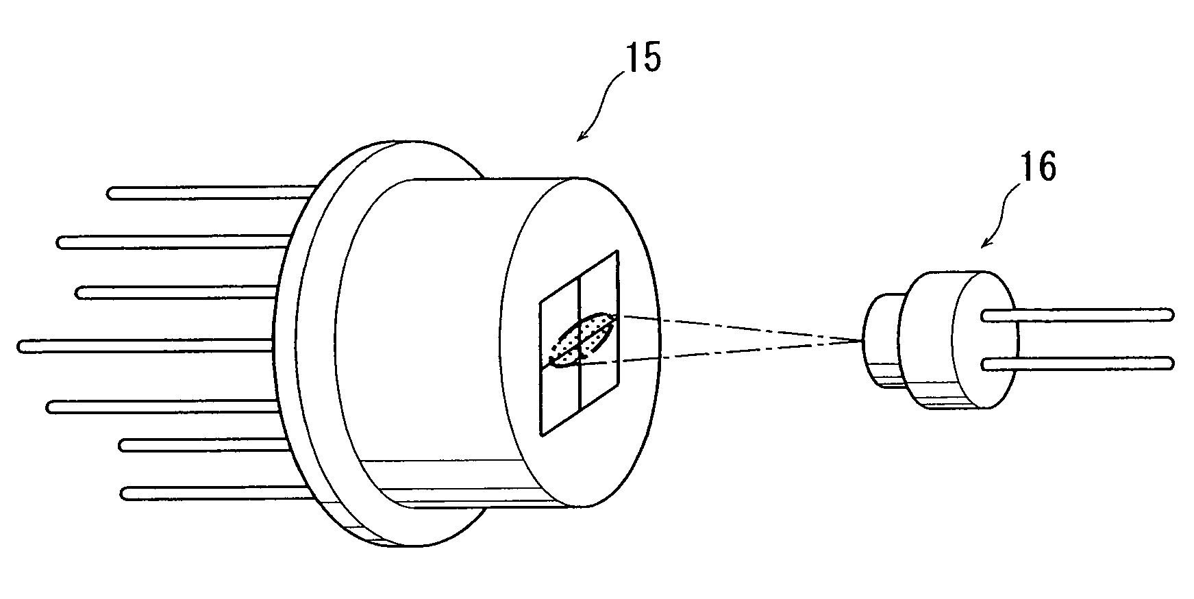
[0051]the present invention will be described with reference to FIG. 10. An optical displacement sensor according to the third embodiment comprises a PD assembly 15 (same as employed in the second embodiment) as a light receiving means, an LED 2 (same as employed in the first embodiment) which is a light emitting element as a light source, and a cylindrical lens 17 disposed between the PD assembly 15 and the LED 2.

[0052]Light emitted from the LED 2, which originally is not shaped oval in cross section, has its cross section modified into an oval configuration with two axes of symmetry when passing through the cylindrical lens 17, and is received at the light receiving face of the PD assembly 15. Since the PD assembly 15 is structured in the same way as in the second embodiment, and since the light received by the PD assembly 15 has an oval cross section like in the second embodiment, rotational adjustment about the Z-axis can be performed following the method described in the second...


PUM

PropertyMeasurementUnit
lengthaaaaaaaaaa
light intensityaaaaaaaaaa
external forceaaaaaaaaaa

Abstract

An optical displacement sensor comprises: a light source; a light receiving means adapted to receive light emitted from the light source; and a light diffracting element disposed between the light source and the light receiving means. The light receiving means include a first light receiving element group centrally located, and a second light receiving element group constituted by two separate clusters disposed so as to sandwich the first light receiving element group, and the light diffracting element functions to diffract the light emitted from the light source along one direction of the two-axis directions into a zero-order beam to be received at the first light receiving element group, and higher-order beams received at the second light receiving element group.

Description

[0001]This application claims priority from Japanese Application No. 2003-316478, filed Sep. 9, 2003 (incorporated by reference herein).BACKGROUND OF THE INVENTION[0002]1. Field of the Invention[0003]The present invention relates to an optical displacement sensor and an external force detecting device, and particularly to an optical displacement sensor which detects relative displacement between a reference object and a measurement object based on displacement of a light reception position, and further to an external force detecting device which detects an external force applied to the measurement object based on a signal outputted from the optical displacement sensor.[0004]2. Description of the Related Art[0005]An external force detecting device, such as a six-axis optical force sensor, is conventionally known, in which a displacement amount of an action section to receive an external force, namely a measurement object, relative to a support section to support the action section, n...

Claims


Application Information

Patent Timeline
Patent Type & Authority Patents(United States)
IPC IPC(8): G01C21/02G01C21/24G01B11/00G01D5/34G01D5/38G01L5/16G02B5/18
CPCG01D5/34G01D5/38G01L5/166
Inventor KITAMURA, ATSUSHIADACHI, SHIGEYUKI
Owner MINEBEAMITSUMI INC
Why Eureka
Try Eureka