Clothes treating apparatus
a technology for treating apparatuses and clothes, which is applied in the direction of defrosting, domestic cooling apparatus, furniture, etc., can solve the problems of enormous electric power consumption, damage to clothes, and ignition of fires in the treating apparatus,
- Summary
- Abstract
- Description
- Claims
- Application Information
AI Technical Summary
Benefits of technology
Problems solved by technology
Method used
Image
Examples
first embodiment
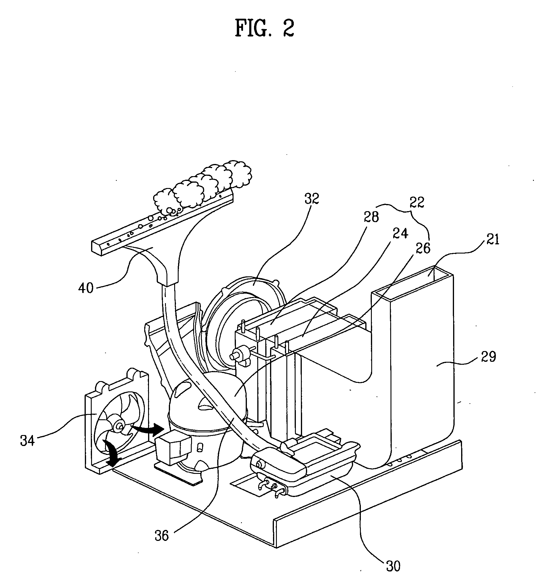
[0039]FIG. 3 is a view schematically illustrating a configuration of the supply unit provided in the clothes treating apparatus according to the present invention.
[0040]Referring to FIG. 3, the supply unit 40 according to the present embodiment includes a supply portion 42 for the ejection of steam, and a water collecting portion 44 having a water collecting path 54 formed at an inner peripheral surface thereof for the collection of condensate water.
[0041]Specifically, the steam is ejected from the supply portion 42 into the accommodating space 12. As described above, the supply portion 42 is located underneath the accommodating space 12 and ejects steam upward.
[0042]The water collecting portion 44 may be tapered downward from an end of the supply portion 42 at a predetermined angle. With a tapered configuration of the water collecting portion 44, the water collecting path 54 for the collection of condensate water is defined at the inner peripheral surface of the water collecting po...
second embodiment
[0049]FIG. 5 is a view schematically illustrating the configuration of a supply unit provided in the clothes treating apparatus according to the present invention.
[0050]Referring to FIG. 5, the steam supply unit 140 according to the second embodiment is different from the first embodiment of FIGS. 3 and 4 in that the water collecting portion 44 is provided with a storage barrier 160. Hereinafter, the second embodiment will be described on the basis of the above difference.
[0051]In the embodiment shown in FIGS. 3 and 4 in which the water collecting path 54 is formed at the inner peripheral surfaces of the water collecting portion 44 and the connecting portion 46, if there exists a small amount of condensed water, it will flow along the water collecting path 54. However, if there exits a large amount of condensate water, there is a likelihood of the condensed water being introduced from a connecting region between the water collecting portion 44 and the connecting portion 46 into the ...
third embodiment
[0056]FIG. 6 is a view schematically illustrating a configuration of a supply unit provided in the clothes treating apparatus according to the present invention.
[0057]Referring to FIG. 6, the supply unit 240 according to the third embodiment is different compared to the above-described embodiments in that a guide is provided at an inner peripheral surface of a connecting portion 246, to guide the flow of condensed water. The guide serves to prevent the condensed water, flowing along the inner peripheral surface of the connecting portion 246, from sputtering toward the center of the connecting portion 246.
[0058]Specifically, in the present embodiment, the guide takes the form of a spiral groove 248 formed at the inner peripheral surface of the connecting portion 246 for guiding the flow of condensed water. Accordingly, once the condensed water is supplied into the connecting portion 246 after flowing along an inner peripheral surface of a water collecting portion 244, the condensed w...
PUM
 Abstract
Description
Claims
Application Information
 - R&D
- Intellectual Property
- Life Sciences
- Materials
- Tech Scout
- Unparalleled Data Quality
- Higher Quality Content
- 60% Fewer Hallucinations
Browse by: Latest US Patents, China's latest patents, Technical Efficacy Thesaurus, Application Domain, Technology Topic, Popular Technical Reports.
© 2025 PatSnap. All rights reserved.Legal|Privacy policy|Modern Slavery Act Transparency Statement|Sitemap|About US| Contact US: help@patsnap.com


