Workplace carrier and conveyor system

a workpiece carrier and conveyor system technology, applied in the direction of conveyors, mechanical conveyors, railway components, etc., can solve the problems of heavy workpiece carriers and expensive friction clutches, and achieve the effects of reducing the risk of soiling the contact rail, avoiding tilting, and preventing a soiling of the electric contacts

Inactive Publication Date: 2009-10-22
CERATIS
View PDF12 Cites 25 Cited by
  • Summary
  • Abstract
  • Description
  • Claims
  • Application Information

AI Technical Summary

Benefits of technology

[0026]Independent of the provision of guide walls or a guide slot, the present guide system comprises an electric contact rail. The electric contact rail is provided in the conveyor path, the contact rail especially being provided on the bottom face of the conveyor path. Thus, it is possible to configure a guide element, also provided below the guide path, with a contact element facing towards the bottom face of the conveyor path and thereby making electric contact with the contact rail. This arrangement of the contact rail, as well as the contact element is especially preferred since it prevents a soiling of the electric contacts.
[0027]In a particularly preferred embodiment, the contact rail is provided at the absorption element of the conveyor system, especially at the bottom face of the absorption element. The contact element, which in this embodiment is preferably connected with the conveyor element of the workpiece carrier, engages into the contact rail preferably from below. This reduces the risk of soiling the contact rail.
[0028]Preferably, the guide element has a T- or L-shaped cross section and is particularly connected with the bottom face of the carrier element. In a preferred embodiment, at least one leg of the guide element engages behind a part of the absorption element on the top surface of which the conveyor path is preferably formed. This not only realizes the guiding of the workpiece carrier, but also avoids tilting. The preferred embodiment is the guide element with a T-shaped cross section, so that tilting in both directions perpendicular to the transport direction is prevented. Here, the guide element preferably abuts against a bottom face of the absorption element.

Problems solved by technology

Moreover, friction clutches are expensive components.
Such workpiece carrier are heavy.
Moreover, such workpiece carrier are disadvantageous, in particular when transporting heavy workpieces, in that the weight of the workpiece also acts on the driven roller, so that the drive shaft is loaded heavily and thus has to be of solid design.

Method used


Image

  • Workplace carrier and conveyor system
  • Workplace carrier and conveyor system
  • Workplace carrier and conveyor system

Examples


Embodiment Construction

with reference to a preferred embodiment and to the accompanying drawings.

BRIEF DESCRIPTION OF THE DRAWINGS

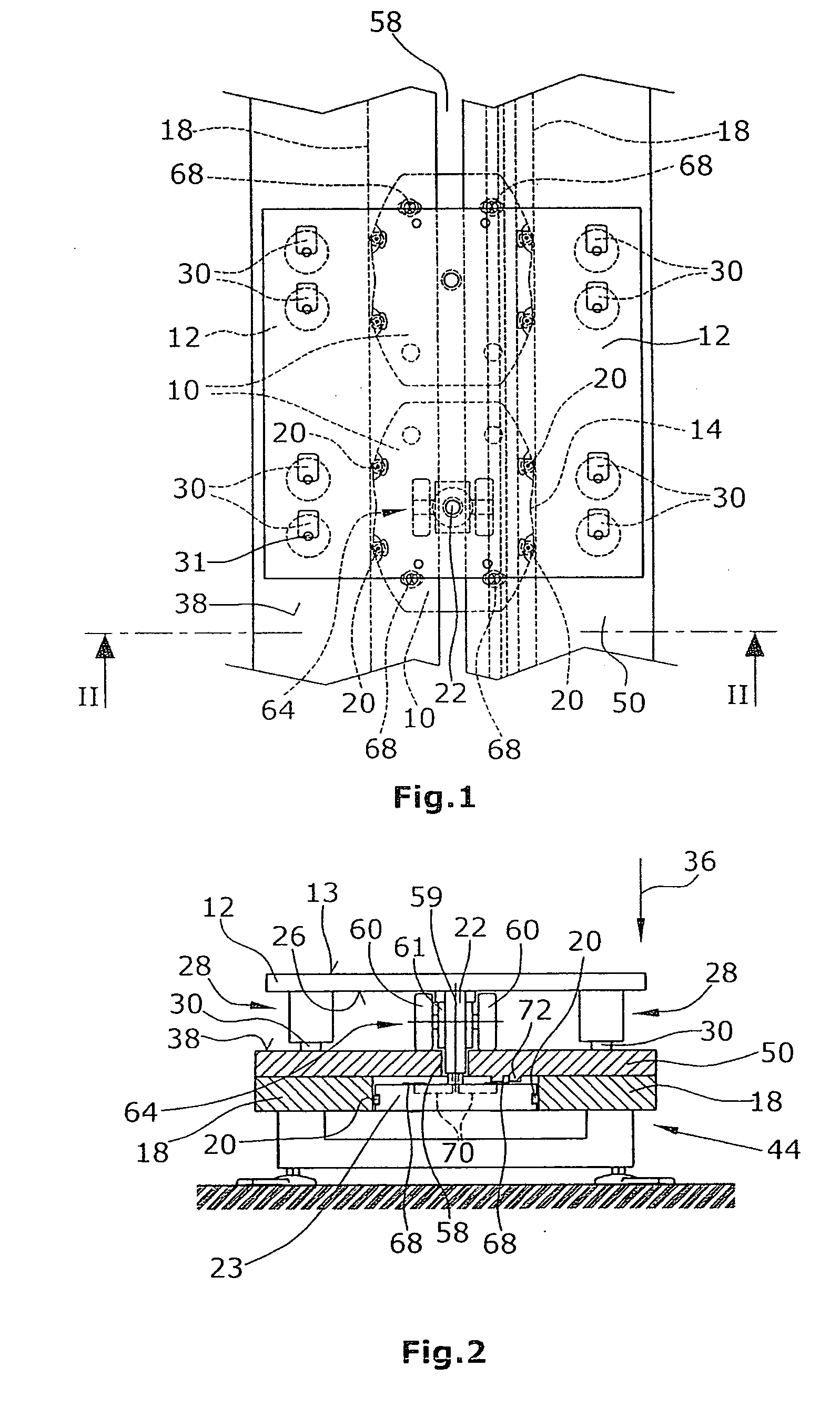
[0030]FIG. 1 is a schematic top plan view on a preferred embodiment of a workpiece carrier,

[0031]FIG. 2 is a schematic side elevational view of the workpiece carrier, seen in the direction of an arrow II in FIG. 1, and

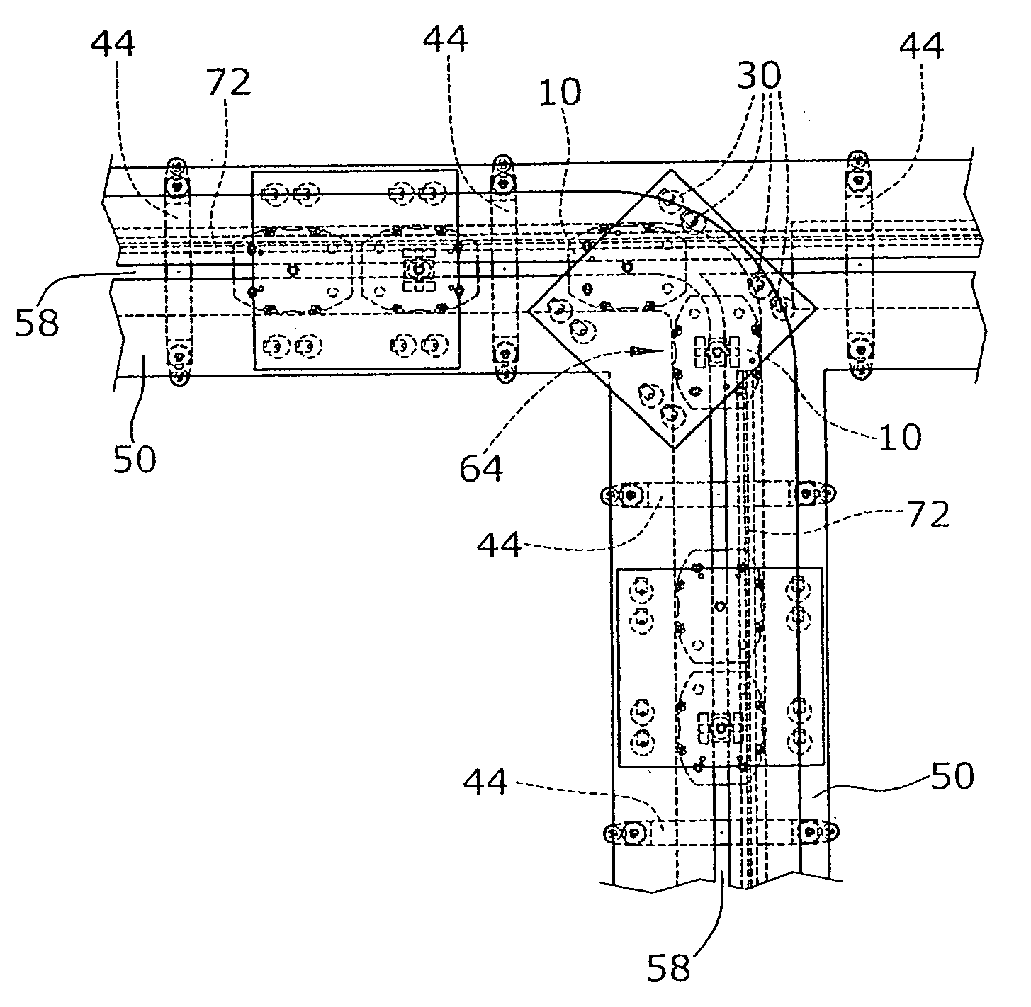
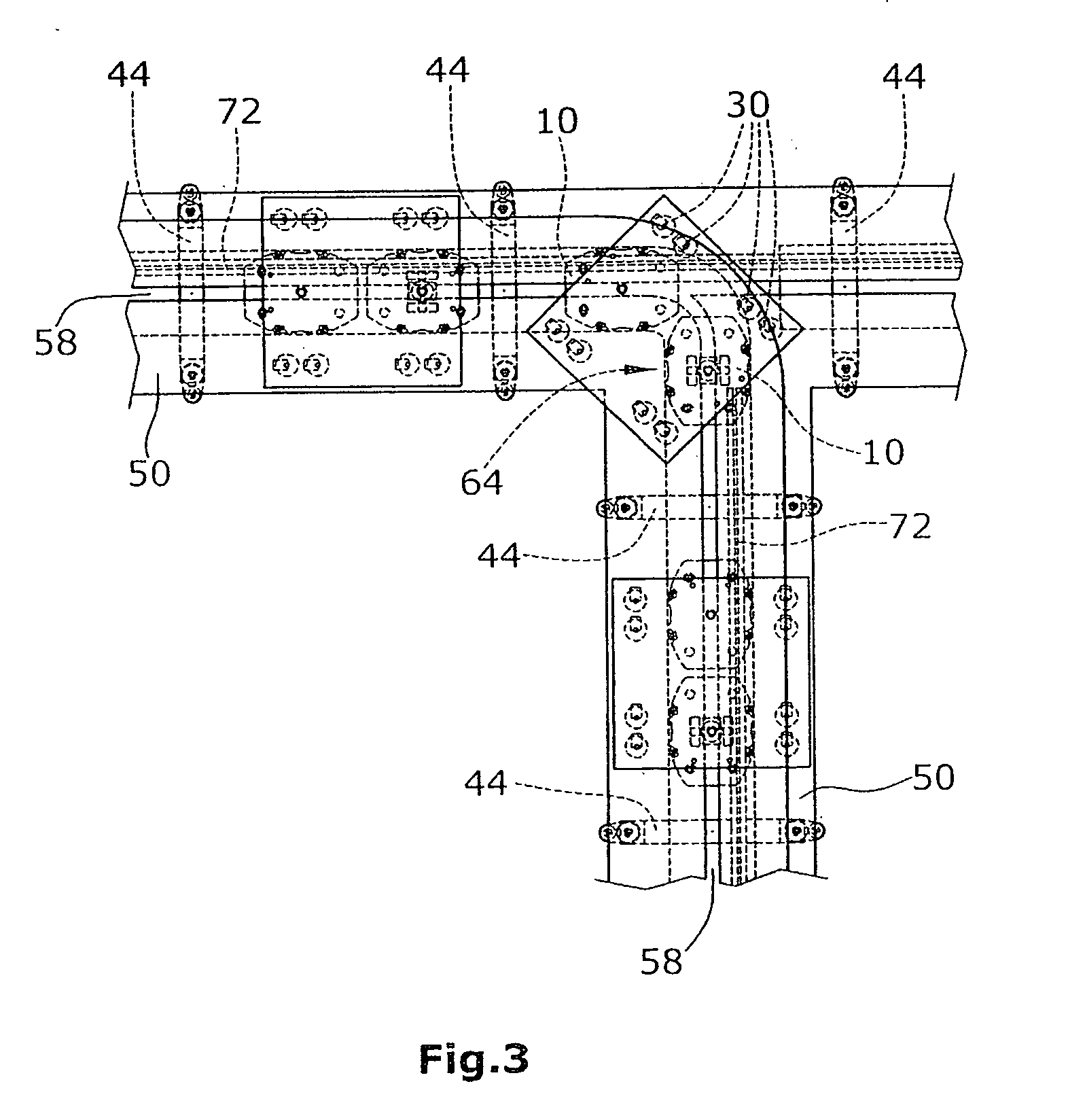
[0032]FIG. 3 is a schematic top plan view on a conveyor system according to the present disclosure.

DETAILED DESCRIPTION OF THE PREFERRED EMBODIMENT

[0033]In the embodiment shown, the workpiece carrier comprises two guide elements 10 connected with a carrier element 12. Here, the guide element are of a T-shaped cross section so that a connection element 22 (FIG. 2) or a corresponding web part for connection with the carrier element 12 is formed. The guide element 10 further comprises a guide shoe 23 connected with the connection element 22. The guide shoe 23 is of plate-shaped design and is arranged substantially in parallel with the carrier element 12. The guide sh...


PUM


Abstract

A workpiece carrier for transporting workpieces on a conveyor path comprises a carrier element for receiving a workpiece. The carrier element is connected with a plurality of support elements for absorbing weight. Further, the carrier element is connected with a guide element in order to guide the carrier element in a load-free manner or without absorption of weight. To form an active, self-propelled workpiece carrier, at least one drive assembly is provided. Drive assembly comprises a drive element resting on a conveyor path.

Description

CROSS-REFERRED APPLICATIONS[0001]This application claims priority to U.S. Provisional Application No. 61 / 126,866, filed on May 8, 2008, which is incorporated herein in its entirety.BACKGROUND[0002]1. Field of the Disclosure[0003]The disclosure refers to a workpiece carrier and a conveyor system comprising such a workpiece carrier.[0004]2. Discussion of the Background Art[0005]Conveyor systems are used, especially in mass production, to transport workpieces between individual workplaces where the workpieces are assembled or treated, for example. To achieve this, the workpieces are placed on workpiece carrier and the workpiece carrier is moved together with the workpieces by corresponding conveyor means. For moving the workpiece carrier, friction conveyors are known, wherein the workpiece carrier are not rigidly secured to the conveyor means, but lie loosely on rolls, belts or plates, for example. The workpiece carriers are moved by friction. It is a particular advantage of friction c...

Claims


Application Information

Patent Timeline
Patent Type & Authority Applications(United States)
IPC IPC(8): B65G17/12B65G47/64
CPCB65G35/06B61B13/00
Inventor KRUPS, MATTHIASKRUPS, PETER
Owner CERATIS
Why Eureka
Try Eureka