Light-emitting module and keyboard

Inactive Publication Date: 2009-10-22
DARFON ELECTRONICS CORP
View PDF4 Cites 16 Cited by
  • Summary
  • Abstract
  • Description
  • Claims
  • Application Information

AI Technical Summary

Benefits of technology

[0006]One aspect of the invention provides a light-emitting module that facilitates assembly and contributes in reductio

Problems solved by technology

However, users usually cannot conveniently operate them in a dark environment or a place where no sufficient light is available.
However, such the electroluminance emits only a

Method used


Image

  • Light-emitting module and keyboard
  • Light-emitting module and keyboard
  • Light-emitting module and keyboard

Examples


Embodiment Construction

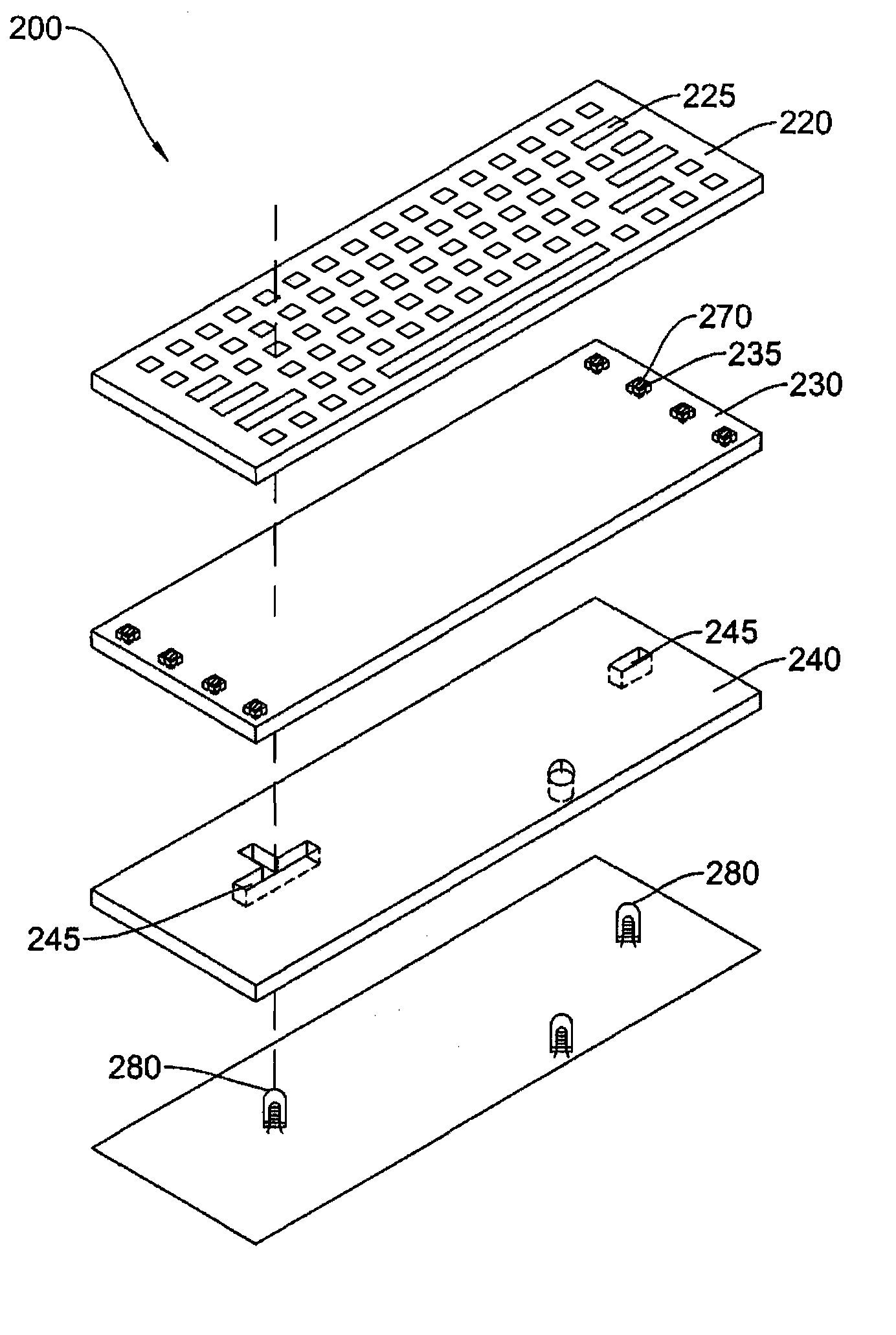
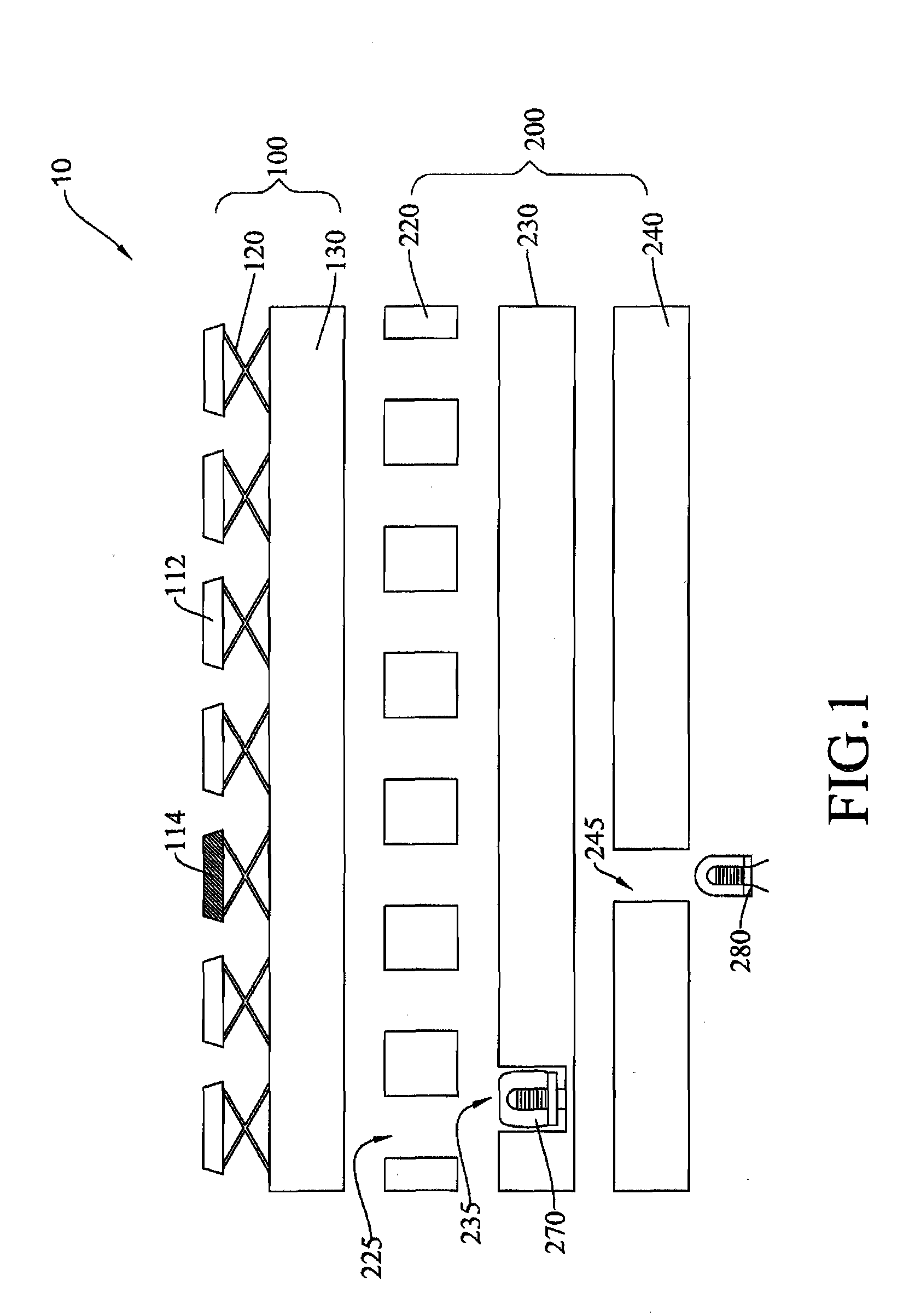
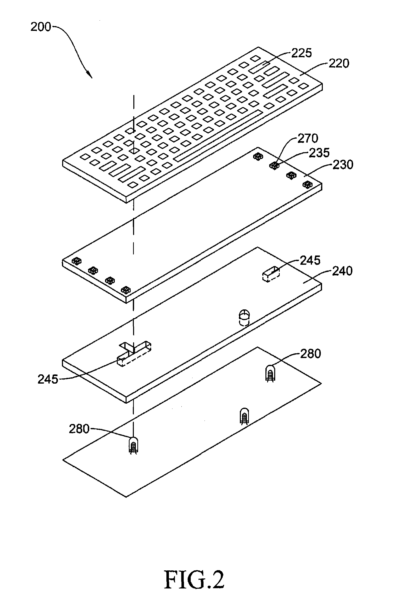
[0017]FIG. 1 is a cross-sectional view illustrating a keyboard 10 in accordance with a first embodiment of the present invention. In the first embodiment, the keyboard 10 refers to that of a laptop or a desktop computer, but is not limited thereto. The keyboard described hereinafter can be any input unit capable of receiving signals, e.g. the keyboard of a mobile phone or the keyboard of an electronic dictionary. The keyboard 10 mainly includes a key module 100 and a light-emitting module 200 there below. The key module 100 is composed of a plurality of keys 112 and 114, a support 120 and a thin circuit board 130, and shows signals that are inputted through the keys 112 and 114 by users in a screen. Alternatively, the key module 100 provides a computer with instructions for controlling programs that are executed.

[0018]As shown in FIG. 1, the light-emitting module 200 is composed of a light-shielding element 220, a first light guide element 230 having a first cavity 235, a first refl...


PUM


Abstract

A keyboard and a light-emitting module therefore are provided. The light-emitting module includes a first light source, a first light guide element, a first reflecting element and a second light source. The first light guide element has a first cavity, and the first light source is disposed in the first cavity. The first reflecting element having at least one opening is disposed under the first light guide element. The second light source is disposed under the first reflecting element, and the light emitted from the second light source passes through the opening.

Description

CROSS REFERENCE TO RELATED APPLICATIONS[0001]This application claims the right of priority based on Taiwan Patent Application No. 97114625 entitled “Light-emitting module and keyboard” filed on Apr. 22, 2008, which is incorporated herein by reference and assigned to the assignee herein.FIELD OF THE INVENTION[0002]This invention relates to a light-emitting module, and more particularly relates to a light-emitting module capable of locally emitting light in different colors and a keyboard therewith.BACKGROUND OF THE INVENTION[0003]Consumer electronics, e.g. computer, electronic dictionary and mobile phone, have been becoming more and more popular in recent decades, and most of them are equipped with a keyboard. However, users usually cannot conveniently operate them in a dark environment or a place where no sufficient light is available.[0004]To continuously operate the keyboard or do the keystrokes, a conventional method employs a electroluminance plate as a light source that is disp...

Claims


Application Information

Patent Timeline
IPC IPC(8): H01H9/00F21V1/00
CPCG02B6/0021G02B6/0055G02B6/0068H01H2219/064H01H2219/014H01H2219/06H01H2219/062H01H13/83
Inventor CHANG, CHAO-LUNG
Owner DARFON ELECTRONICS CORP
Why Eureka
Try Eureka