Light-concentrating panel

Inactive Publication Date: 2009-10-22
NAT TAIWAN UNIV OF SCI & TECH
View PDF25 Cites 11 Cited by
  • Summary
  • Abstract
  • Description
  • Claims
  • Application Information

AI Technical Summary

Benefits of technology

[0006]An objective of the present invention is to provide a light-concentrating panel capable of collecting light from the outdoors (e.g. sun's rays) and transmitting into a house so as to save energy, rather than turning on the lamps in daytime.
[0010]The light-concentrating panel of the present invention can turn planar light or light from arbitrary direction into spot light, also can transmit light in reverse direction, i.e. spot light to planar light. Therefore, the present invention has better results in light compression and light dispersion.
[0011]The light-concentrating panel of the present invention can be attached or mounted on a roof or an outer wall of the building for collecting light from the outdoors (e.g. sun's rays) and directing to the house. Since the light-concentrating panel can be attached to the outer wall of the building, the light-concentrating panel can be served as a type of building materials. It may be pleasant to see and also saves spaces. In addition, for safety concerns, stronger wind may not a serious problem. When the light-concentrating panel is made of an acrylic material, the cost is lower than those light collectors coating with silver. In addition, the process to manufacture the light-concentrating panel is not complicated. The light-concentrating plane of the present invention has advantages of lower cost, mass production, and is beneficial for carrying out environment-friendly buildings.

Problems solved by technology

Since many buildings today are poorly illuminated, there is a need to switch on light in daytime, and this results in a waste of electricity.
However, the installation of the solar lighting device 10 or the light reflection device 202 of the energy saving lighting device 20 are limited to the construction of the building because they are too bulky to be installed easily and may impair the outer appearance.
Moreover, their reflecting surfaces are usually silver plated, and this results in high cost.
Stronger wind may bring about a serious concern for safety.

Method used


Image

  • Light-concentrating panel
  • Light-concentrating panel
  • Light-concentrating panel

Examples


Embodiment Construction

[0023]The present invention will be described in details in conjunction with the appending drawings.

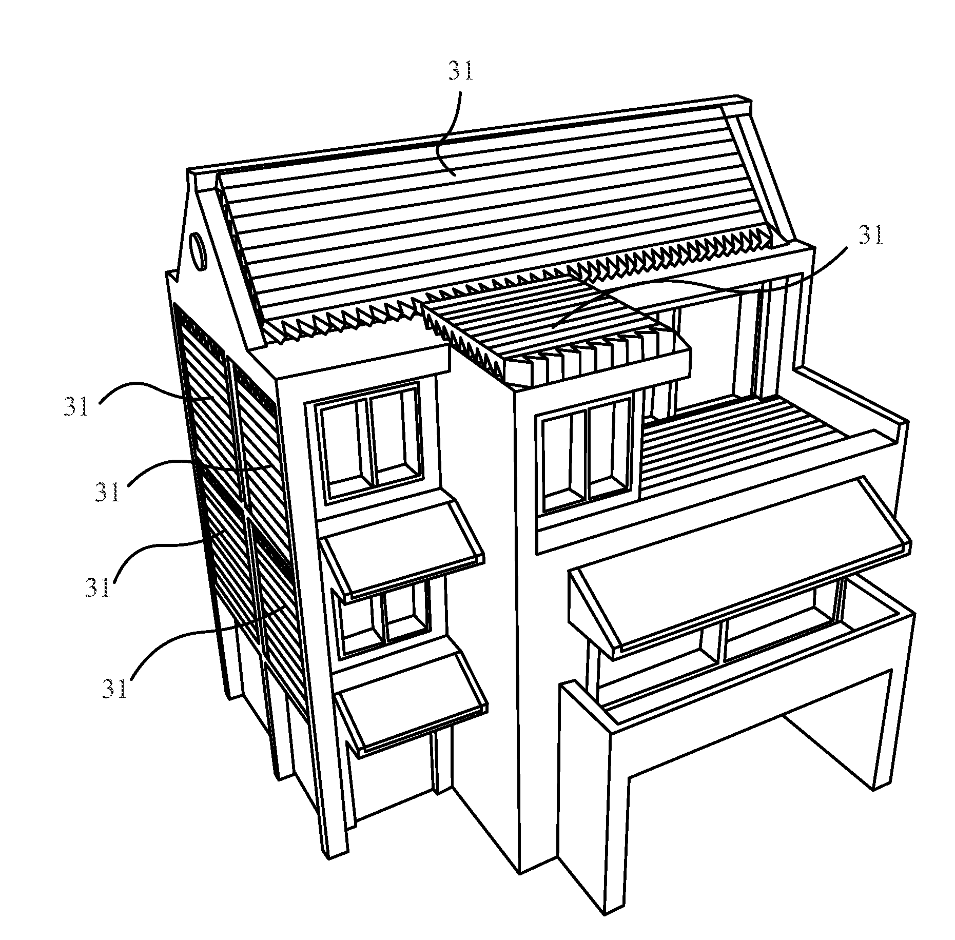
[0024]Referring to FIG. 3, which is a schematic diagram showing a light-concentrating panel 31 of the present invention attached to a building. The light-concentrating panel 31 of the present invention can be mounted on a roof or an outer wall where it can receive light from the outdoors. The light-concentrating panel 31 may be designed adequately or may be capable of being cut or assembled to an appropriate size so as to fit different regions of the outer of the building.

[0025]The light-concentrating panel 31 of the present invention is divided into two parts. As shown in FIG. 4, the light-concentrating panel 31 comprises a planar light collecting element 313 and a linear light collecting element 319. The two elements 313, 319 can be integrated as one. Since the integrated structure has no joining interface existed therebetween, this kind of structure can avoid internal reflection pr...


PUM


Abstract

A light-concentrating panel is disclosed. The light-concentrating panel comprises a planar light collecting element and a linear light collecting element. The planar light collecting element receives and collects the planar light, and then emits out as linear light. The linear light collecting element receives the linear light. The linear light from the planar collecting element enters the linear light collecting element by passing a planar-linear imaginary plane, which is located between the planar light collecting element and the linear light collecting element. The linear light from the planar collecting element are collected and turned into the spot light by the linear light collecting element.

Description

TECHNICAL FIELD OF THE INVENTION[0001]The present invention relates to a light-concentrating panel, and more particularly, to a light-concentrating panel capable of collecting planar light and turning it into spot light.BACKGROUND OF THE INVENTION[0002]Since many buildings today are poorly illuminated, there is a need to switch on light in daytime, and this results in a waste of electricity. To address this problem, adequate indoor lighting or daylighting is gradually being taken seriously.[0003]Referring to FIG. 1, which is a schematic diagram showing a conventional solar lighting device 10. The solar lighting device 10 comprises a collecting plate 102, a reflecting plate 104, and a guiding tube 106. For the above mentioned, sun's rays are collected by the collecting plate 102, reflected by the reflecting plate 104, and then gathered at an opening of the guiding tube 106. Finally, the guiding tube 106 transmits sun's rays into a room E. Referring to FIG. 2, which is a schematic dia...

Claims


Application Information

Patent Timeline
IPC IPC(8): G02B27/09G02B5/04
CPCE04C2/54F21S11/00F24J2/062G02B6/0038G02B6/0016G02B6/0028G02B5/045F24S23/10
Inventor WHANG, ALLEN JONG-WOEICHEN, YI-YUNGWU, BO-YICHUANG, CHUN-HSIENCHO, CHUN-HSIENYU, CHEN-MINGCHEN, HSI-CHI
Owner NAT TAIWAN UNIV OF SCI & TECH
Why Eureka
Try Eureka