Connector having a sleeve member

a technology of connectors and sleeves, applied in the direction of coupling device connections, coupling protective earth/shielding arrangements, coupling parts engagement/disengagement, etc., can solve the problem that the size of the push-pull connector may not meet certain industry standards, the process for molding and manufacturing the components of the push-pull connector may be costly, and the compressible plastic material does not provide electrical shielding for the connection. the effect of less cos

Active Publication Date: 2009-10-22
TYCO ELECTRONICS LOGISTICS AG (CH)
View PDF27 Cites 107 Cited by
  • Summary
  • Abstract
  • Description
  • Claims
  • Application Information

AI Technical Summary

Benefits of technology

[0006]Accordingly, there is a need for a push-pull connector that forms an environmental seal and / or an electrical shield while satisfying predetermined requirements. Furthermore, there is a need for a push-pull connector that may be constructed in a less costly manner than other known connectors.

Problems solved by technology

The resulting size of the push-pull connector may not satisfy certain industry standards.
Furthermore, the process for molding and manufacturing the components of the push-pull connector may be costly.
In addition, the compressible plastic material does not provide electrical shielding for the connection.

Method used


Image

  • Connector having a sleeve member
  • Connector having a sleeve member
  • Connector having a sleeve member

Examples


Embodiment Construction

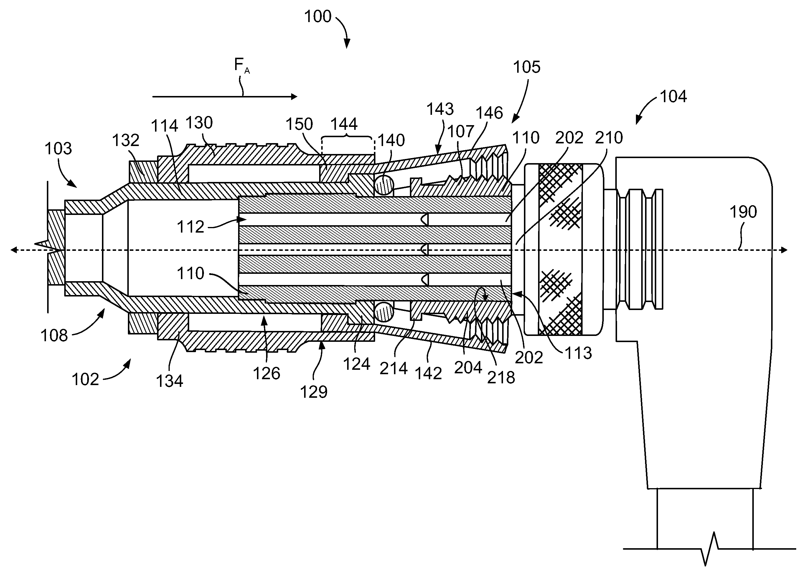
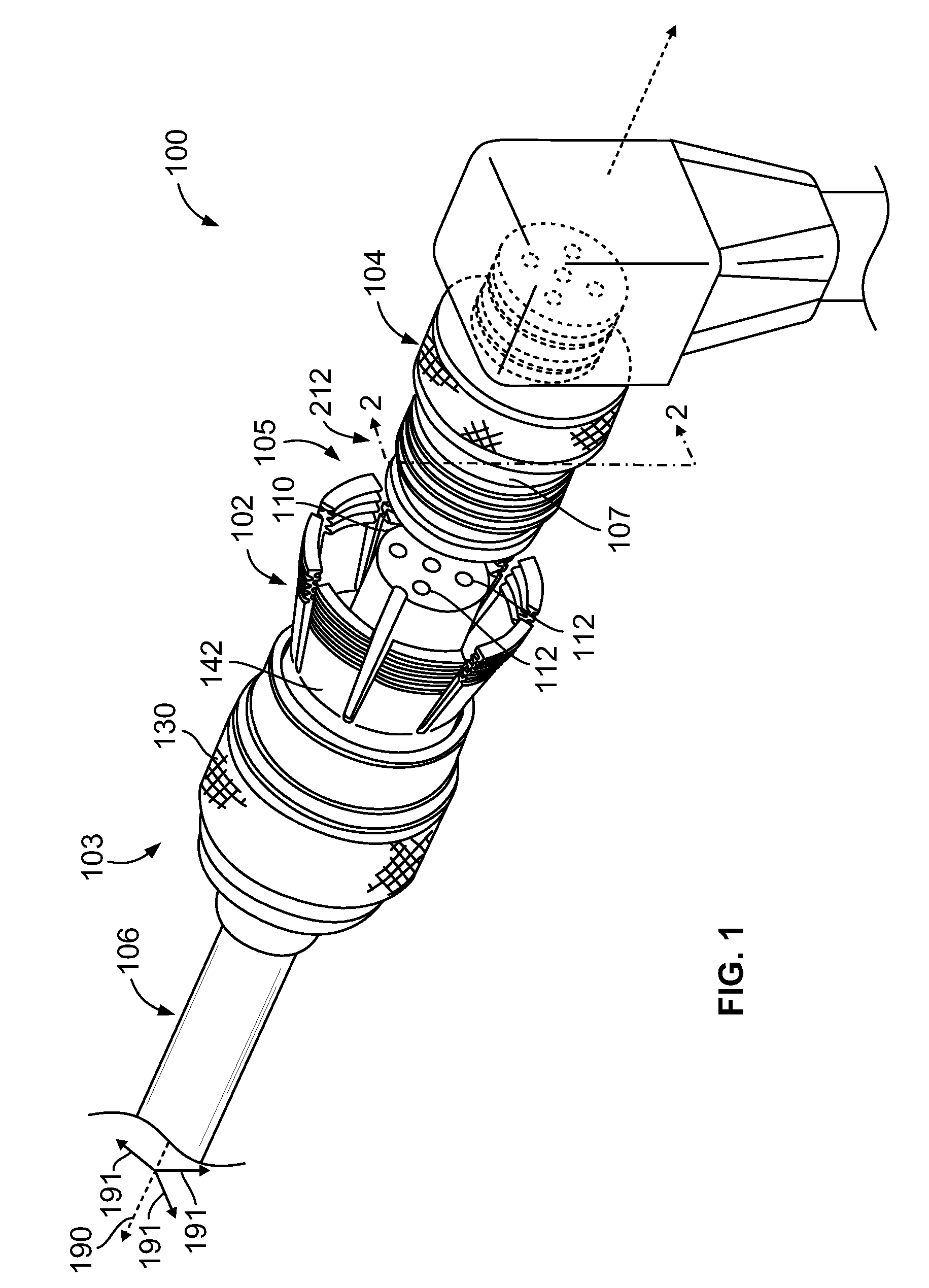
[0021]FIG. 1 is a perspective view of a connector system 100 formed in accordance with one embodiment. The connector system 100 is used to connect a cable assembly 106 to an electrical device or system (not shown) and includes a connector assembly 102 (also referred to as a push-pull connector or first connector) and a mating connector 104 (also referred to as a second connector). In FIG. 1, the connector assembly 102 is disengaged from the mating connector 104. The connector assembly 102 extends between a loading end 103 and a mating end 105 and extends along a longitudinal or central axis 190. The connector assembly 102 may include a plug body 110, a sleeve member 142 that surrounds the plug body 110, and a collar 130 that surrounds the sleeve member 142. The collar 130 is configured to slide between a withdrawn position (shown in FIG. 1) to a locked position (shown in FIG. 5). The connector assembly 102 may include other components and features, such as those described in U.S. pa...


PUM


Abstract

A connector assembly configured to sealably engage with a mating connector. The connector assembly includes a plug assembly that has a mating end configured to be inserted into the cavity of the mating connector. The connector assembly also includes a collar that surrounds the plug assembly. The connector assembly also includes a sleeve member that is positioned between the collar and the plug assembly. The sleeve member surrounds the plug assembly about the central axis and includes a plurality of fingers that extend toward the mating end. The sleeve member is stamped and formed from a common piece of sheet material. The fingers are biased away from the central axis in a flared arrangement when the collar is in the withdrawn position. The lingers press against the wall surface of the mating connector when the collar is moved from the withdrawn position to the locked position.

Description

CROSS-REFERENCE TO RELATED APPLICATIONS[0001]The present application claims priority to and is a continuation-in-part of U.S. patent application Ser. No. 12 / 104,551, filed Apr. 17, 2008, which is incorporated by reference in the entirety.[0002]The present application also includes subject matter that is similar to subject matter disclosed in a U.S. patent application having Attorney Docket No. E-GI-00537 (958-4012US), which is filed contemporaneously with the present application and is incorporated by reference in the entirety.BACKGROUND OF THE INVENTION[0003]The invention relates generally to connectors, and more particularly to connectors that form an environmental seal around an electrical or fiber optic connection.[0004]Push-pull type connectors may provide a quick method for establishing a communicative and / or power connection between systems and devices. In one known push-pull type connector, the connector has a cylindrical body that is configured to mate with a mating connect...

Claims


Application Information

Patent Timeline
Patent Type & Authority Applications(United States)
IPC IPC(8): H01R13/62H01R13/648
CPCH01R13/5219H01R13/6277H01R13/6275
Inventor HERTZLER, CHRISTOPHERWALKER, ROBERTLENKER, WILLIAM
Owner TYCO ELECTRONICS LOGISTICS AG (CH)
Why Eureka
Try Eureka