
Method and apparatus for removing winding conductors from a twisting machine and placing them in a rotor or stator stack

a technology of winding conductors and twisting machines, applied in the direction of electrical apparatus, winding conductor shape/form/construction, dynamo-electric machines, etc., can solve the problems of high labor intensity, slow process described above, and inability to meet the needs of mass production motors

Active Publication Date: 2009-10-29
TECNOMATIC
View PDF33 Cites 44 Cited by
  • Summary
  • Abstract
  • Description
  • Claims
  • Application Information

AI Technical Summary

Problems solved by technology

However, the procedure described above is slow and highly labor intensive, and not suitable for a mass produced motor.

Method used


Image

  • Method and apparatus for removing winding conductors from a twisting machine and placing them in a rotor or stator stack
  • Method and apparatus for removing winding conductors from a twisting machine and placing them in a rotor or stator stack
  • Method and apparatus for removing winding conductors from a twisting machine and placing them in a rotor or stator stack

Examples


Embodiment Construction

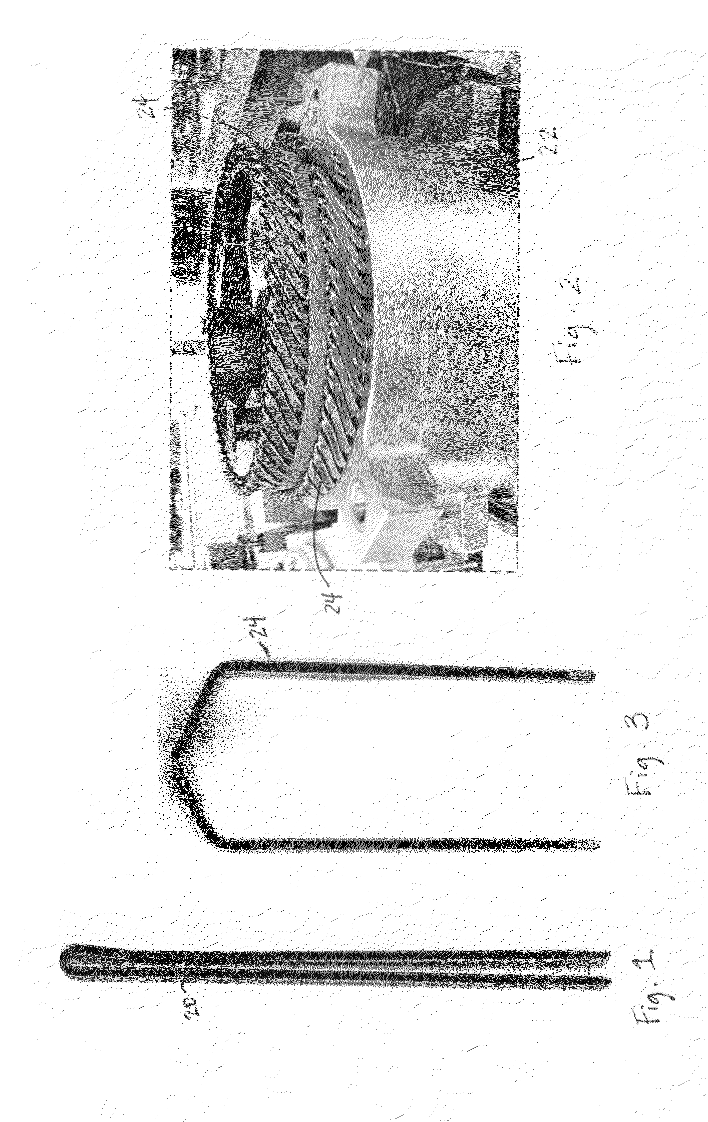
[0020]The purpose of the present invention is to simultaneously remove all rectangular winding conductors from a twisting fixture and to place the same in the desired rotor or stator core. In particular, a rectangular insulated conductor with ends stripped is bent into a hairpin conductor 20 as shown in FIG. 1. Then all conductors required, except in the case of special length stator conductors used for phase connections in AC motors, are simultaneously bent into rotor or stator conductors 24 (FIG. 3) in the twisting fixture 22 of FIG. 2. After the twisting operation, the conductors 24 reside in fixture 22, with the fixture 22 having a sufficient depth so that the ends of conductors 24 are still within pockets within the fixture. In that regard, the word “pockets” as used herein is used in the general sense to include not only an enclosure on all sides but to further include slots which are open on one side.

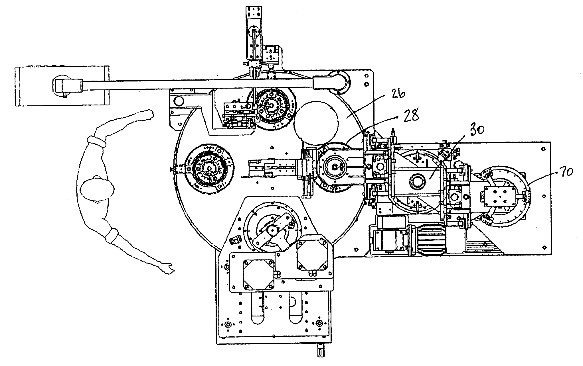
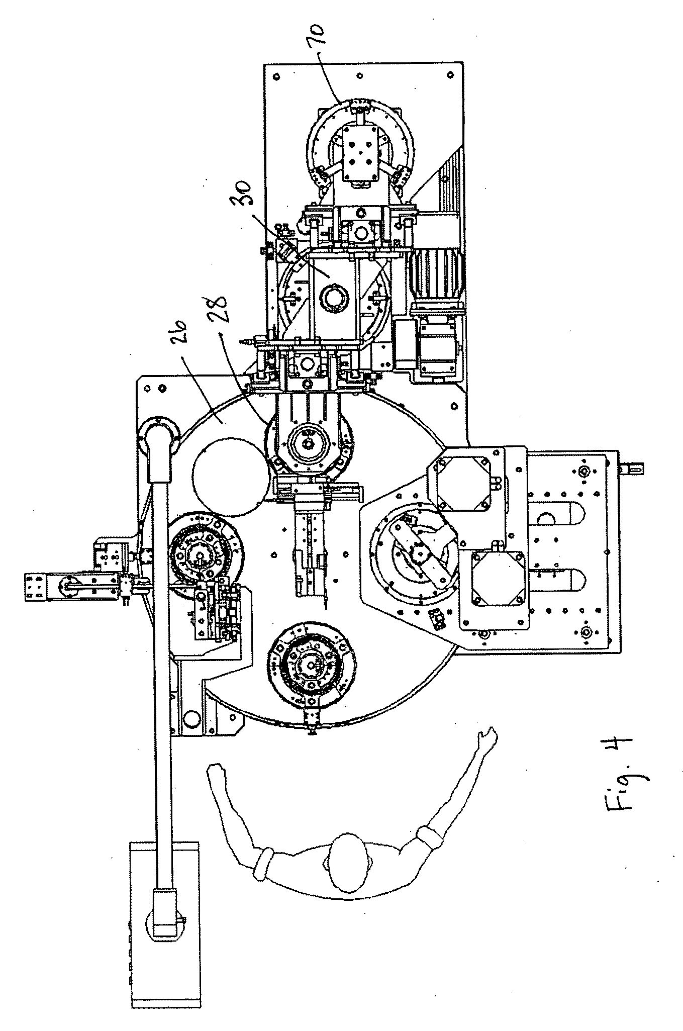
[0021]A top view of the overall system in which the present invention is use...


PUM

PropertyMeasurementUnit
distanceaaaaaaaaaa
surface tensionaaaaaaaaaa
electric field concentrationaaaaaaaaaa

Abstract

Method and apparatus for removing winding conductors from a twisting machine and placing them in a rotor or stator stack. The method comprises, for removing from a twisting fixture and inserting into a rotor or stator, a plurality of rectangular winding conductors each having a pair of legs separated by an amount equal to the distance between a predetermined number of rotor or stator slots in which they will be inserted and integrally connected at one end thereof, moving a plurality of fingers of a clamping assembly between the legs of a plurality of winding conductors in a twisting fixture to retain the winding conductors, moving the clamping assembly away from the twisting fixture to withdraw the winding conductors from the twisting fixture, providing relative movement of the clamping assembly and a rotor or stator to insert free ends of the winding conductors into a rotor or stator, and moving the fingers of a clamping assembly from between the legs of a plurality of winding conductors. A preferred embodiment of the apparatus is also disclosed.

Description

BACKGROUND OF THE INVENTION[0001]1. Field of the Invention[0002]The present invention relates to the field of electric motors.[0003]2. Prior Art[0004]Tecnomatic S.p.A., assignee of the present invention, has in the past made a limited number of motor stators and D.C. motor rotors using flat or square wire for the windings. In that regard, it is to be noted that as used herein, “flat” or “square” wire means wire having four substantially flat sides, each joined to adjacent sides, typically by a rounded edge. In the case of square wire, the wire may be formed in the square shape and then coated with typical winding insulation, or in some cases, pre-coated round wire has been rolled into the square shape. Rolling of round wire to a square shape has definite limits if the insulation is not to be damaged, though smaller rounded edges may be achieved if the wire is first formed by drawing or otherwise formed into the square shape and then coated. Even if the wire is first formed in the de...

Claims


Application Information

Patent Timeline
Patent Type & Authority Applications(United States)
IPC IPC(8): B23P11/00
CPCH02K15/0428H02K15/063Y10T29/49012Y10T29/53157Y10T29/49817Y10T29/49009H02K15/064
Inventor GUERCIONI, SANTE
Owner TECNOMATIC
Features
  • Generate Ideas
  • Intellectual Property
  • Life Sciences
  • Materials
  • Tech Scout
  • Unparalleled Data Quality
  • Higher Quality Content
  • 60% Fewer Hallucinations
Learn More