Hot water system

a technology of hot water system and hot water pump, which is applied in the direction of heating types, positive displacement liquid engines, instruments, etc., can solve the problems of water waste, installation space and power supply safety, and users have to wait, so as to increase the water pressure, save water, and fast hot water supply

Active Publication Date: 2009-10-29
LEE YU TUAN
View PDF8 Cites 27 Cited by
  • Summary
  • Abstract
  • Description
  • Claims
  • Application Information

AI Technical Summary

Benefits of technology

[0008]Regarding the above-mentioned problems, it is an objective of the invention to provide an apparatus, which can provide a water recirculation without changing the layout of water piping systems. Thus, the user can enjoy fast hot water supply as well as saving the water. In this invention, there are cold water pipes, hot water pipes, a water heater, a pump, a pump control unit and a mix faucet with an outlet control valve. In the conventional water piping system, the cold water pipes connect to the water heater's inlet, and the hot water pipes connect to the water heater's outlet. The invention inserts a pump between the cold water pipes and the water heater, the pump control unit controls the pump to increase the water pressure in the hot water pipes, and the water pressure is kept at a higher preset level than the water pressure of the cold water pipes. The fixtures at the terminals of the piping system, which connects to both the cold water pipes and hot water pipes (such as the mix faucet with an outlet control valve), is used to form a closed channel for connecting the cold water pipes and the hot water pipes, and so to form a recirculation path. With the pump control unit which can detect the water pressure difference and the water temperature, and by detecting the water pressure difference change when the cold water pipes and hot water pipes are connected, the pump is controlled and able to recirculate the water in the pipes until the hot water is available.

Problems solved by technology

The user has to wait and the water is wasted.
But this kind of solution must install a pump under every sink that needs fast hot water, and for a shower room faucet there are problems in installation space and in the power supply safety.

Method used


Image

  • Hot water system
  • Hot water system
  • Hot water system

Examples


Embodiment Construction

[0014]The present invention will be apparent from the following detailed description, which proceeds with reference to the accompanying drawings, wherein the same references relate to the same elements.

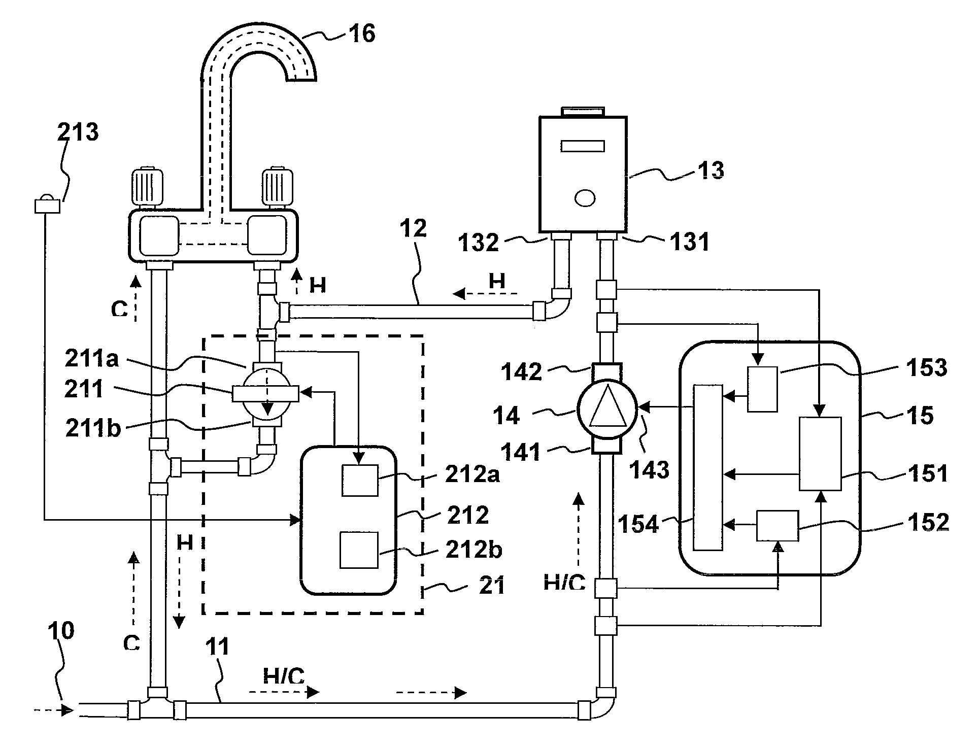
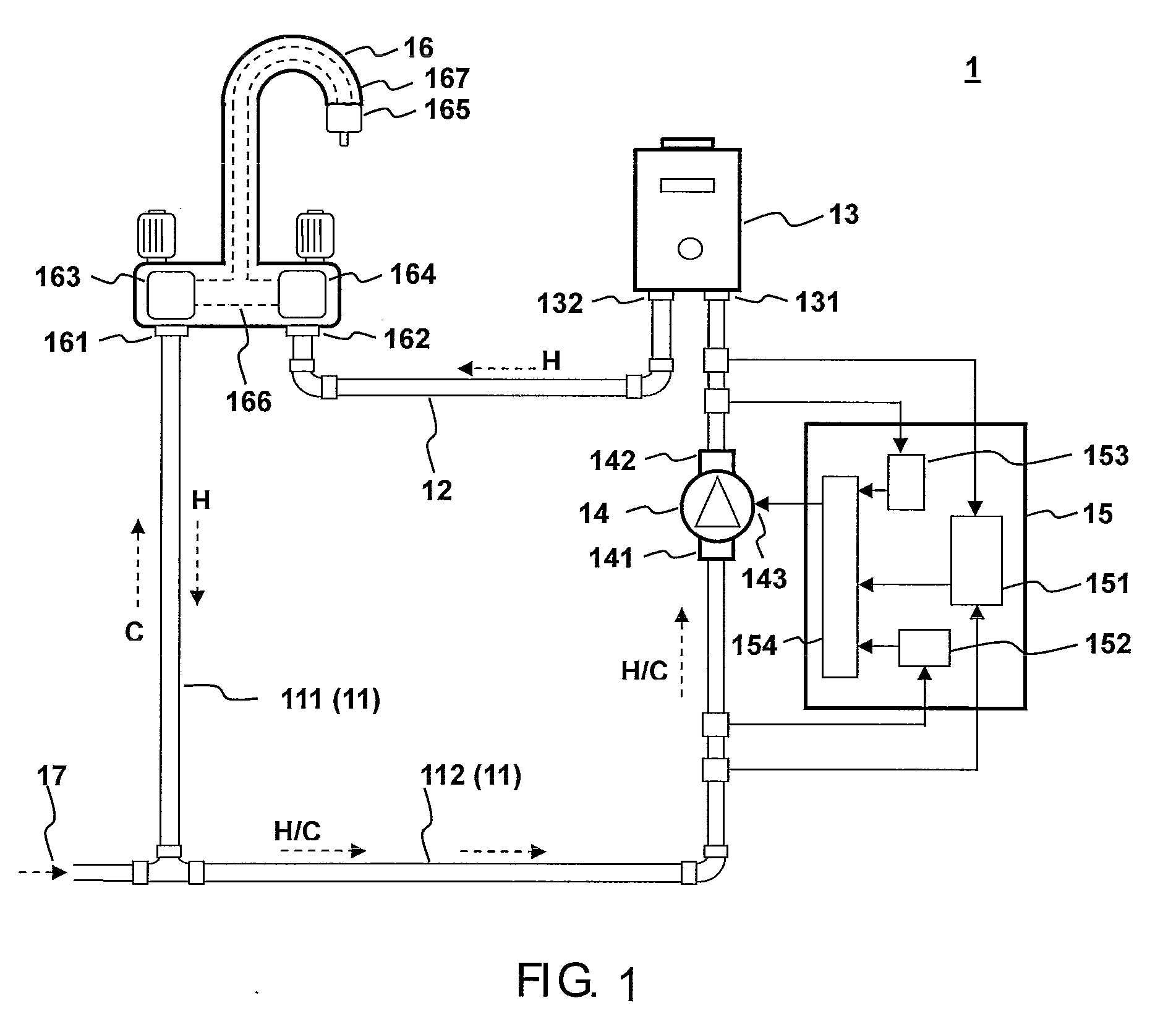
[0015]Referring to FIG. 1, the hot water system of the invention consists of cold water pipes 11, hot water pipes 12, a water heater 13, a pump 14, a pump control unit 15, a mix faucet 16 and water mains 17. The water heater 13 has a cold water inlet 131 and a hot water outlet 132. The pump 14 has a water inlet 141, a water outlet 142 and a power supply input 143. The pump control unit 15 has a water pressure detector 151, a water temperature detector 152, a water flow detector 153 and a pump control circuit 154. The mix faucet 16 has a cold water inlet 161, a hot water inlet 162, a cold water control valve 163, a hot water control valve 164, an outlet control valve 165, a water outlet 167 and a water mix chamber 166. The hot water inlet 162 connects to the hot water pipes 12, and the...


PUM


Abstract

A hot water system includes cold water pipes, hot water pipes, a water heater, a pump, a pump control unit and a connection valve unit. The pump is used to increase the pressure of the hot water pipes to a preset higher level than the pressure in the cold water pipes. When hot water is needed, the connection valve unit at the user side is opened to connect the cold water pipes and the hot water pipes, and when the cold water pipes and the hot water pipes are connected, the water pressure difference between them will become smaller. When the pressure difference change is detected, the pump control unit will activate the pump to pump the water in the hot water pipes into the cold water pipes, so the water in the pipes starts to circulate, and the water will flow through the water heater and will be heated. When the heated hot water reaches the user, the pump is stopped. After the hot water is being served or when the water temperature drops down, the pump is again put into normal operation.

Description

CROSS REFERENCE TO RELATED APPLICATIONS[0001]This Non-provisional application claims priority under 35 U.S.C. §119(a) on Patent Application No(s). 097115778 filed in Taiwan, Republic of China on Apr. 29, 2008, the entire contents of which are hereby incorporated by reference.BACKGROUND OF THE INVENTION[0002]1. Field of Invention[0003]This invention relates to a hot water system which uses the cold and hot water recirculation to provide a fast hot water supply and avoid the waste of water.[0004]2. Related Art[0005]Conventional domestic hot water supply system uses a water heater to heat up the water from the cold water pipes, and flows to the fixtures through hot water pipes, such as the faucets in the bathroom or kitchen. When using the hot water at the first time, there is a lot of cold water in the hot water pipes, the user has to open the faucet and drain the cold water before he gets the hot water. The user has to wait and the water is wasted. As for this water wasting problem, ...

Claims


Application Information

Patent Timeline
Patent Type & Authority Applications(United States)
IPC IPC(8): F16K49/00F16K21/00F04B49/10F04B49/00
CPCF24D17/0078Y10T137/6497Y10T137/7737Y10T137/86397Y10T137/9464
Inventor LEE, YU-TUAN
Owner LEE YU TUAN
Why Eureka
Try Eureka