Wear detection device for conveyor belt

a technology of wear detection and conveyor belt, which is applied in the direction of alarms, instruments, conveyor parts, etc., can solve the problems of increasing the size and cost of the devi

Inactive Publication Date: 2009-10-29
BRIDGESTONE CORP
View PDF5 Cites 19 Cited by
  • Summary
  • Abstract
  • Description
  • Claims
  • Application Information

AI Technical Summary

Problems solved by technology

In EP 0 753 472A1, the transponders are widely embedded so that the size and cost of the device increase.

Method used


Image

  • Wear detection device for conveyor belt
  • Wear detection device for conveyor belt
  • Wear detection device for conveyor belt

Examples


Embodiment Construction

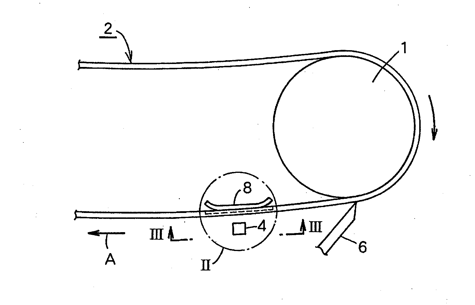
[0014]FIG. 1 is a side elevational view of an unloading side end of a belt conveyor comprising the first embodiment according to the present invention.

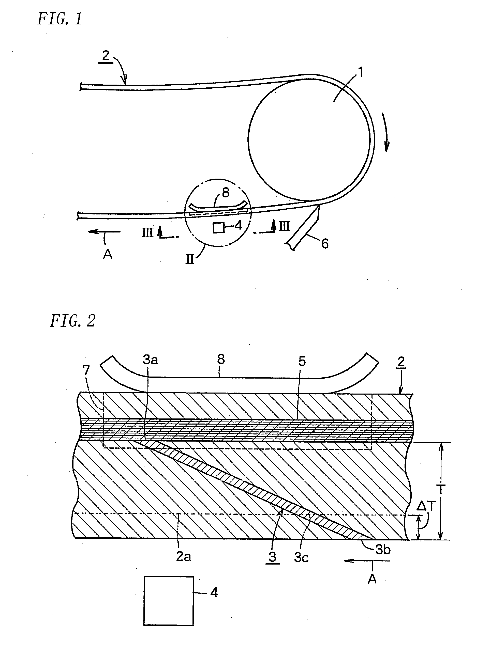
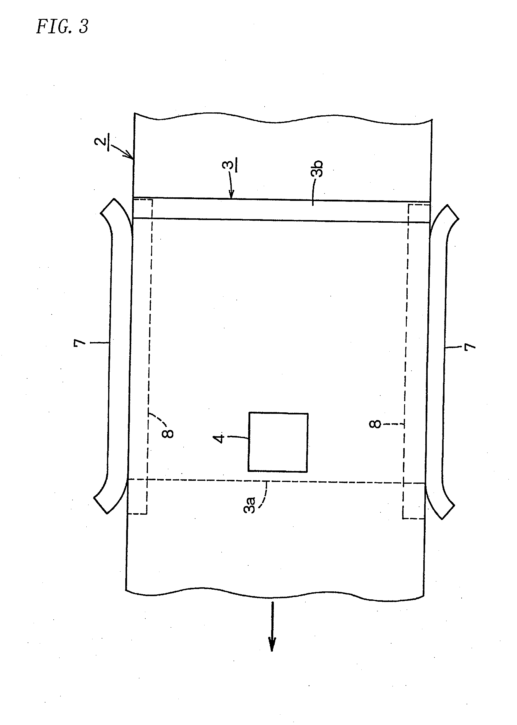
[0015]FIG. 2 is an enlarged vertical sectional side view of the part II in FIG. 1; and an enlarged view seen from the line III-III in FIG. 1.

[0016]A wear detector comprises a rubber magnet 3 embedded in a conveyor belt 2 wound on a pulley 1; and a magnetic sensor 4 detecting magnetic force from the rubber magnet 3.

[0017]The rubber magnet 3 comprises a plate magnetized along its thickness and embedded with an inclination upward in a running direction as shown by an arrow in FIGS. 1 and 2. As shown in FIG. 2, the proximal end 3a of the rubber magnet 3 contacts a reinforcement 5 and the distal end 3b is exposed on the surface of the conveyor belt 2, so that the rubber magnet 3 is embedded over a whole width of the conveyor belt 2.

[0018]The rubber magnet 3 comprises a bonded magnet in which magnet powder is dispersed and mixed in a rubber...


PUM


Abstract

A wear detection device for a conveyor belt capable of automatically, easily, and accurately detecting the wear amount of the conveyor belt during the operation, formed in a simple structure, and manufacturable at low cost. A rubber magnet (3) magnetized in the thickness direction is buried in the conveyor belt (2) diagonally relative to both the advancing and thickness directions of the conveyor belt. A magnetic sensor (4) detecting the change of a magnetic force due to the wear of the rubber magnet (3) resulting from the wear of the conveyor belt (2) is disposed at a position through which the rubber magnet (3) is passed.

Description

TECHNICAL FIELD[0001]The present invention relates to a wear detector of a conveyor belt for detecting wear without contact to the conveyor belt.BACKGROUND OF THE INVENTION[0002]To detect wear of a conveyor belt, JP2004-35115A discloses a wear detector of a conveyor belt in which a wear detecting layer in the belt having different color such as white rubber from an elastic layer of the belt is embedded, exposure of the wear detecting layer enabling wear to be found.[0003]A supersonic wave thickness meter determines thickness of a conveyor belt periodically to find wear when the conveyor belt does not run.[0004]EP 0 753 472A1 or DE19 525 326A discloses that a plurality of transponders are embedded at different depths, any of the transponders broken or dropped out being detected by an antenna comprising a transmitting coil and a sensing coil close to the running belt to enable wear of the belt to be found.[0005]However, in JP2004-35115A or supersonic wave thickness meter, instead of d...

Claims


Application Information

Patent Timeline
Patent Type & Authority Applications(United States)
IPC IPC(8): B65G43/02
CPCB65G2203/0275B65G43/02
Inventor NISHIKITA, YUKINOBU
Owner BRIDGESTONE CORP
Why Eureka
Try Eureka