Rotolock cervical plate locking mechanism

a cervical plate and locking mechanism technology, applied in the field of bone fixation devices, can solve problems such as pain, infection, and/or possible death of patients

Inactive Publication Date: 2009-10-29
HAWKES DAVID T
View PDF4 Cites 24 Cited by
  • Summary
  • Abstract
  • Description
  • Claims
  • Application Information

AI Technical Summary

Benefits of technology

[0006]According to one exemplary embodiment, an orthopedic bone fixation device for stabilizing a plurality of bone segments includes a bone plate and a screw assembly. The bone plate includes a body defining at least one thru-bore, wherein the thru-bore is defined to include a central cavity, the central cavity includes a split ring, a compliant member, or another positionable element configured to modify an exit diameter of the thru-bore. Additionally, an actuation member is coupled to the bone plate. According to one exemplary embodiment, actuation of the actuation member, either by rotation, sliding, or the like, causes the actuation member to engage the positionable member, thereby modifying the exit diameter of the thru-bore. Further, the screw assembly is configured to be coupled to the bone plate, wherein the screw assembly includes a bone screw having a head section and a thread section. When actuated, the positionable element is configured to reduce the exit diameter of the thru-bore sufficient to interfere with the head section of the bone screw, thereby preventing the screw from backing out.

Problems solved by technology

Due to its relative location to the esophagus and other connective tissue, if the screw securing the plate to the cervical spine backs out, the screw could irritate or even pierce the esophagus, resulting in pain, infection, and / or possible death of the patient.

Method used


Image

  • Rotolock cervical plate locking mechanism
  • Rotolock cervical plate locking mechanism
  • Rotolock cervical plate locking mechanism

Examples


Embodiment Construction

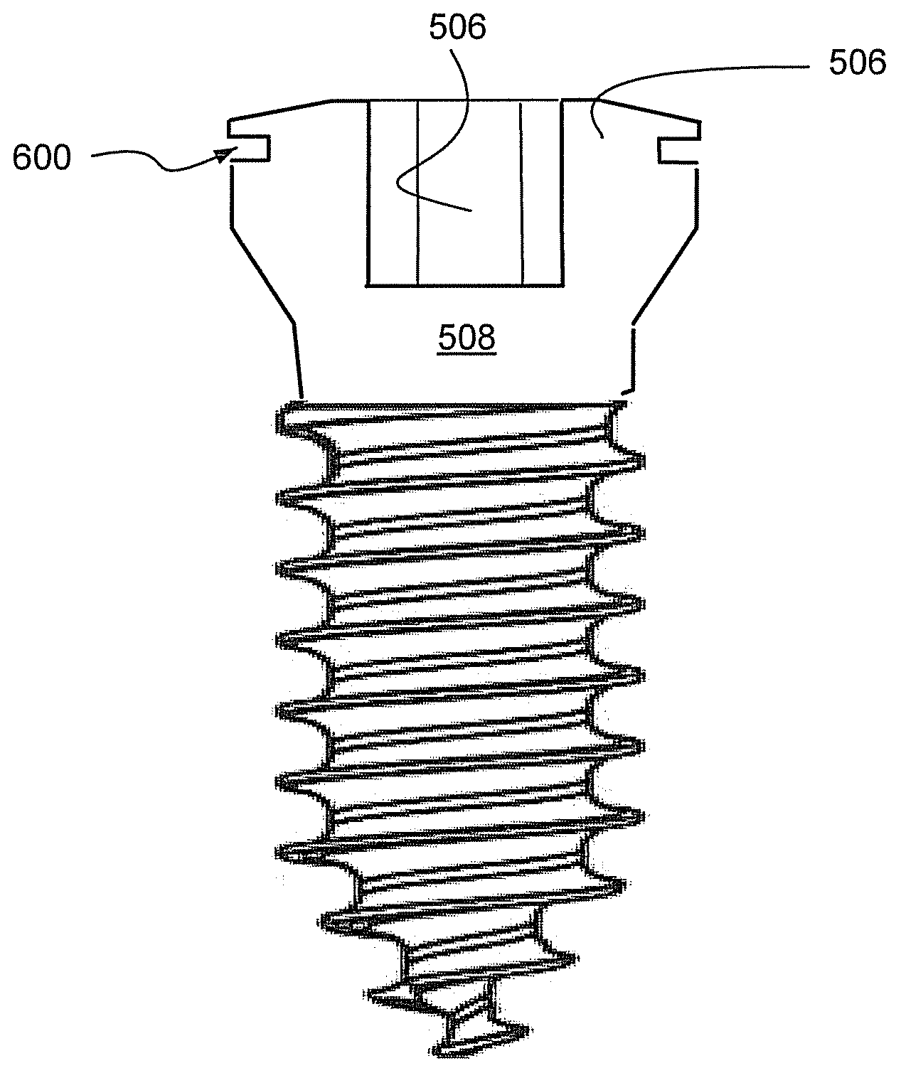
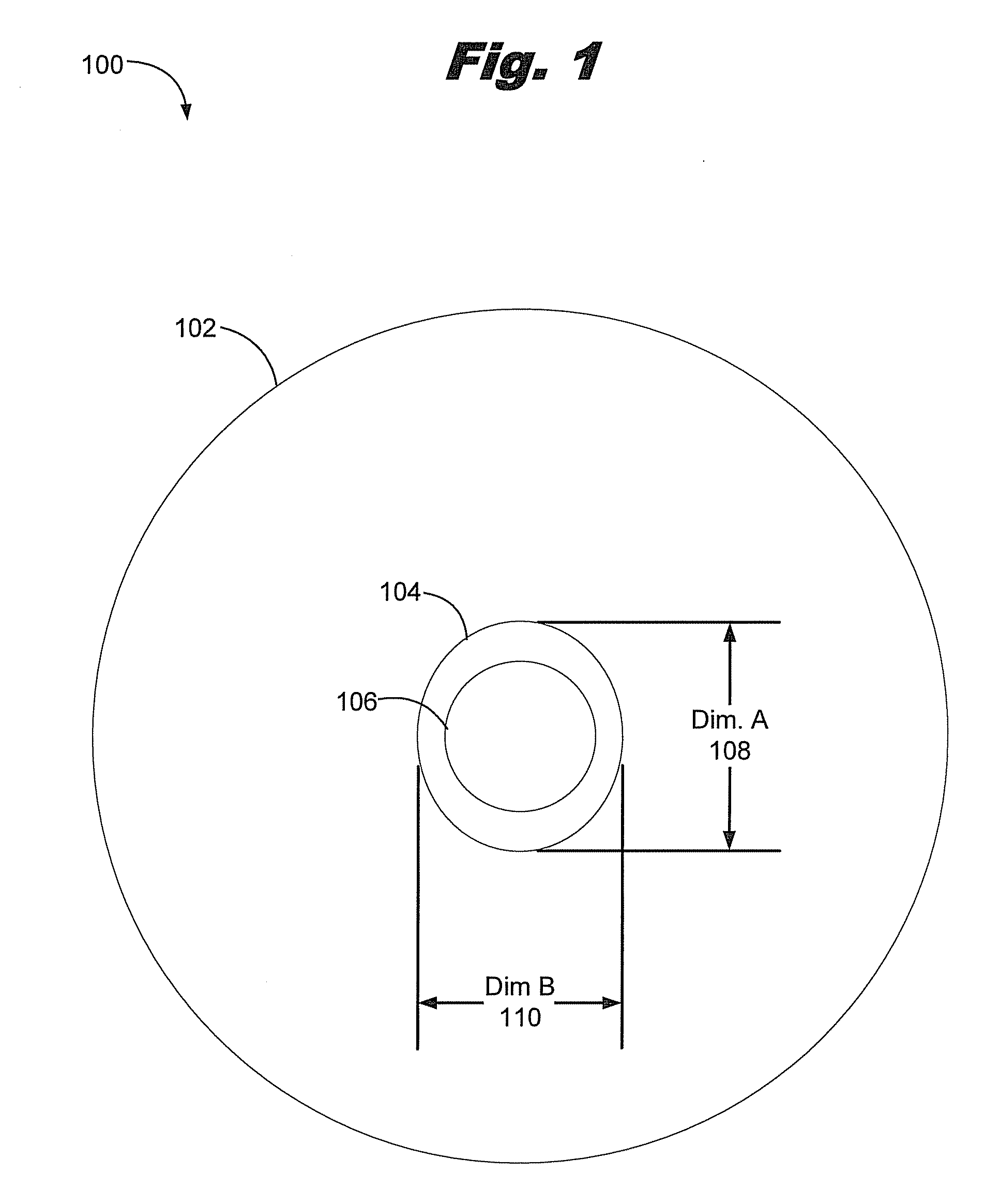
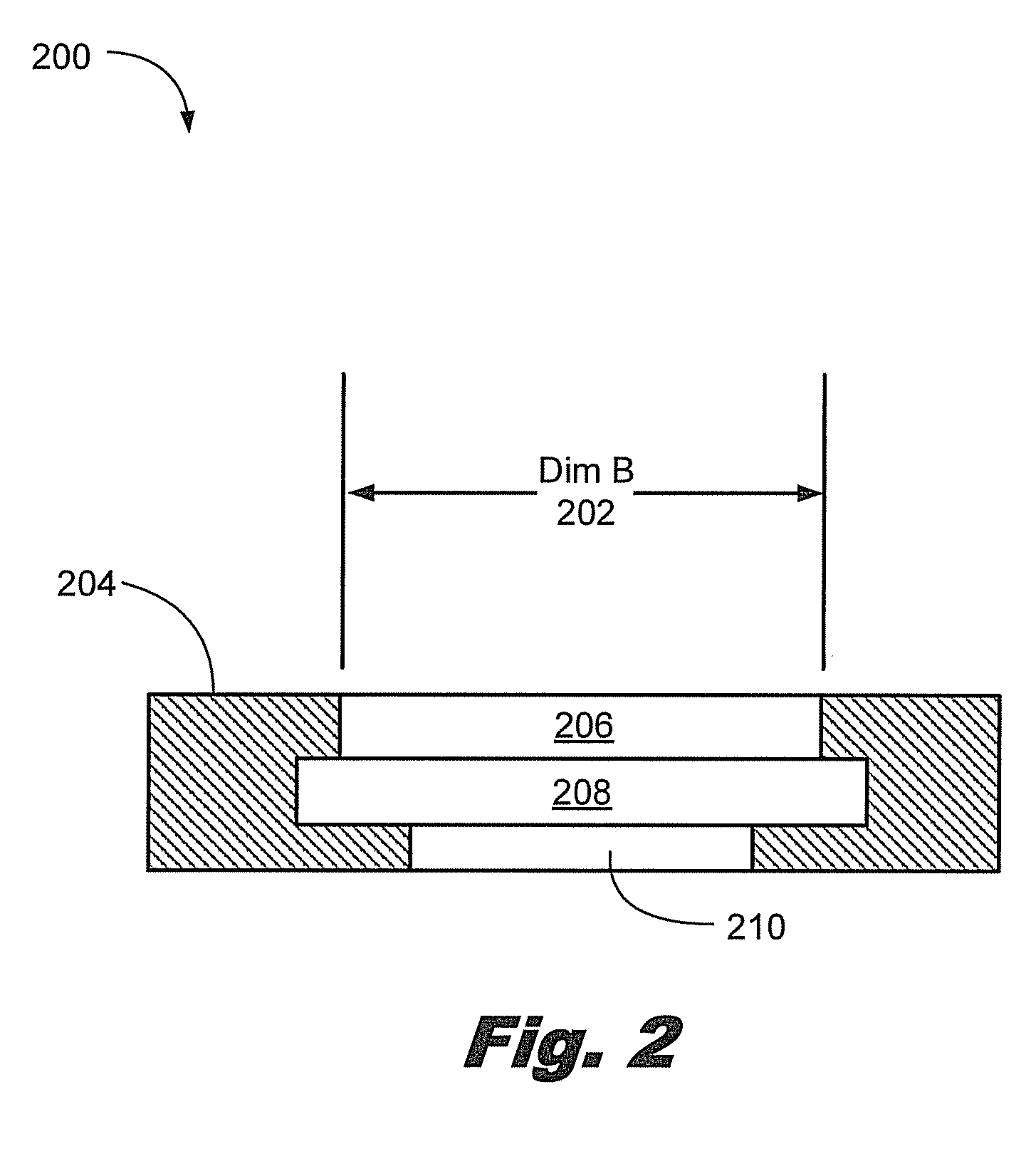
[0018]The present specification describes a system and a method for preventing screws used in orthopedic devices from backing out. According to one exemplary embodiment, an oval shaped compressible retention member, such as a split-ring is placed inside an oval shaped slot on an orthopedic plate where a screw is to be inserted. Once the screw has been driven into place, the positionable element may be rotated to reduce the diameter of its inner edge, thereby covering the screw and preventing it from backing out of the orthopedic plate. As used herein, for ease of explanation only, the present system and method will be described in terms of a compression occurring from the selective rotation of an oval compressible member within an oval orifice. However, it will be understood that the present exemplary system and method may be performed by the rotation of a compressible retention member having a non-circular perimeter in a non-circular orifice.

[0019]By way of example, orthopedic plat...


PUM


Abstract

An orthopedic plate contains a thru-bore with an oval shaped rim and an internal groove underneath that rim. A compressible retention member is designed with an upper plane and a lower plane. The upper plane being oval shaped and smaller in diameter than the lower plane. The lower plane is designed to extend into the internal groove cut into the orthopedic device. After the screw has been inserted, the compressible retention member is rotated, squeezing the larger dimension of the oval shaped ring into the smaller dimension of the oval shaped rim. This reduces the diameter of the compressible retention member. The compressible retention member has an overhang section that when compressed, covers up part of the top edge of the screw to prevent it from backing out.

Description

RELATED APPLICATIONS[0001]This application claims the benefit under 35 U.S.C. § 119(e) of U.S. Provisional Patent Application No. 61 / 047,684 filed Apr. 24, 2008 titled “Rotationally Activated Oval Locking Ring and Undercut Screw Feature,” which provisional application is incorporated herein by reference in its entirety.FIELD[0002]The present system and method relate to bone fixation devices. More particularly, the present system and method provide for an orthopedic system including a plate, a screw system, and a complete system including the plate system, the screw system, and the screw retention system.BACKGROUND[0003]In the treatment of various spinal conditions, including the treatment of fractures, tumors, and degenerative conditions, it is necessary to secure and stabilize the spine following removal of a vertebral body or part. Various devices for internal fixation of bone segments in the human or animal body are known in the art.[0004]Following such removal made using a thora...

Claims


Application Information

Patent Timeline
Patent Type & Authority Applications(United States)
IPC IPC(8): A61B17/80A61B17/86
CPCA61B17/8047
Inventor HAWKES, DAVID T.
Owner HAWKES DAVID T
Why Eureka
Try Eureka