
Automatic Steering System For An Agricultural Implement

Active Publication Date: 2009-11-05
CNH IND CANADA
View PDF24 Cites 43 Cited by
  • Summary
  • Abstract
  • Description
  • Claims
  • Application Information

AI Technical Summary

Benefits of technology

[0027]In some embodiments, the method of steering the agricultural implement further comprises the step of reorienting the first ground-engaging wheel to substantially minimize the creation of the non-covered area.

Problems solved by technology

While wide planters reduce the amount of time required to plant a field, planters with large widths make it difficult if not impossible to transport the planters to and from fields to be planted.
In this regard, when a planter hitch is extended and wing assemblies are folded into the transport position, the ground engaging wheels on the central frame assembly are far away from the end of the hitch linked to a tractor, which means that the tractor / planter assembly has an extremely large turning radius in this configuration.
A large turning radius can be particularly problematic when turning off a narrow road and through a narrow pass into a field or when maneuvering through other tight spots.
Planting operations for large fields may require an extensive amount of time to complete, such as several hours, and in the case of manually controlled vehicles, the operator must constantly steer the vehicle to ensure proper planting coverage.
Improper planting coverage may result in lost revenues for the operator or, if additional passes are used to address unplanted areas, higher fuel costs.
As a result, operators typically invest a large amount of effort to ensure all areas of a field are properly covered without requiring additional passes.
However, the effort required to constantly steer a manually controlled tractor for a long period of time can easily fatigue an operator.
However, the effectiveness of automatically controlled tractors is limited because the path of the planter is indirectly controlled by the tractor.
As a result, the planter may not provide proper planting coverage in some situations.
For example, automatically controlled tractors may not provide proper planting coverage in strip-till operations.
However, the planting units may not be appropriately positioned relative to the rows even if the tractor follows the same path for tilling and planting due to, for example, an uneven field surface.

Method used


Image

  • Automatic Steering System For An Agricultural Implement
  • Automatic Steering System For An Agricultural Implement
  • Automatic Steering System For An Agricultural Implement

Examples


Embodiment Construction

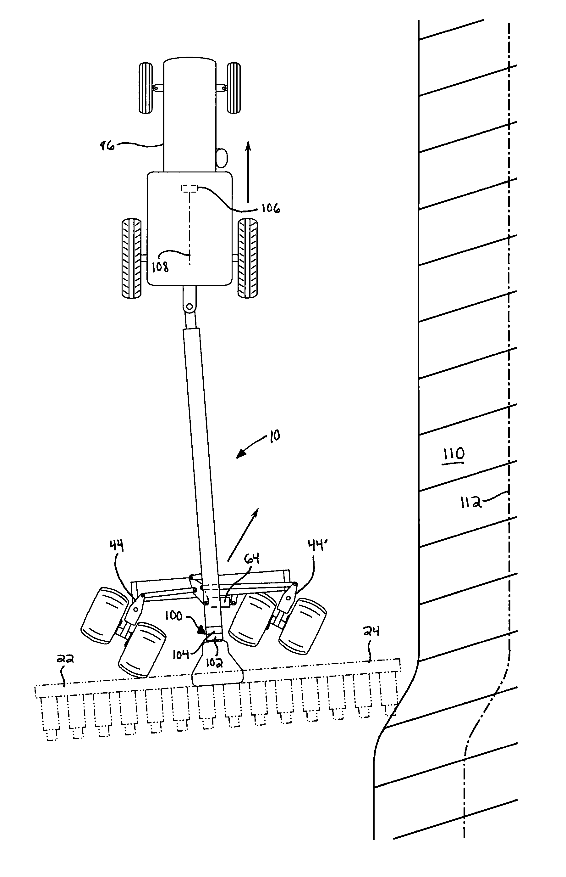
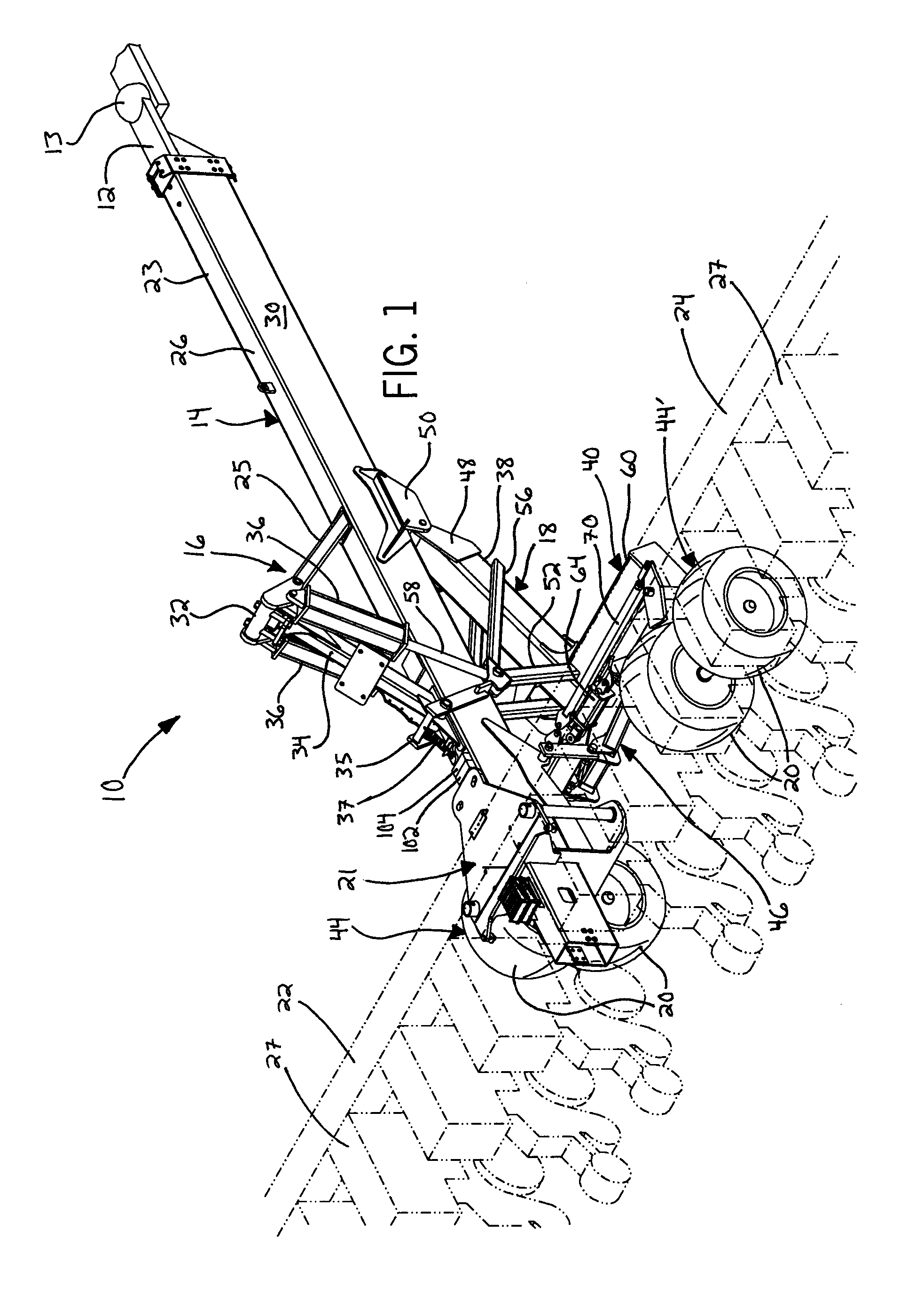
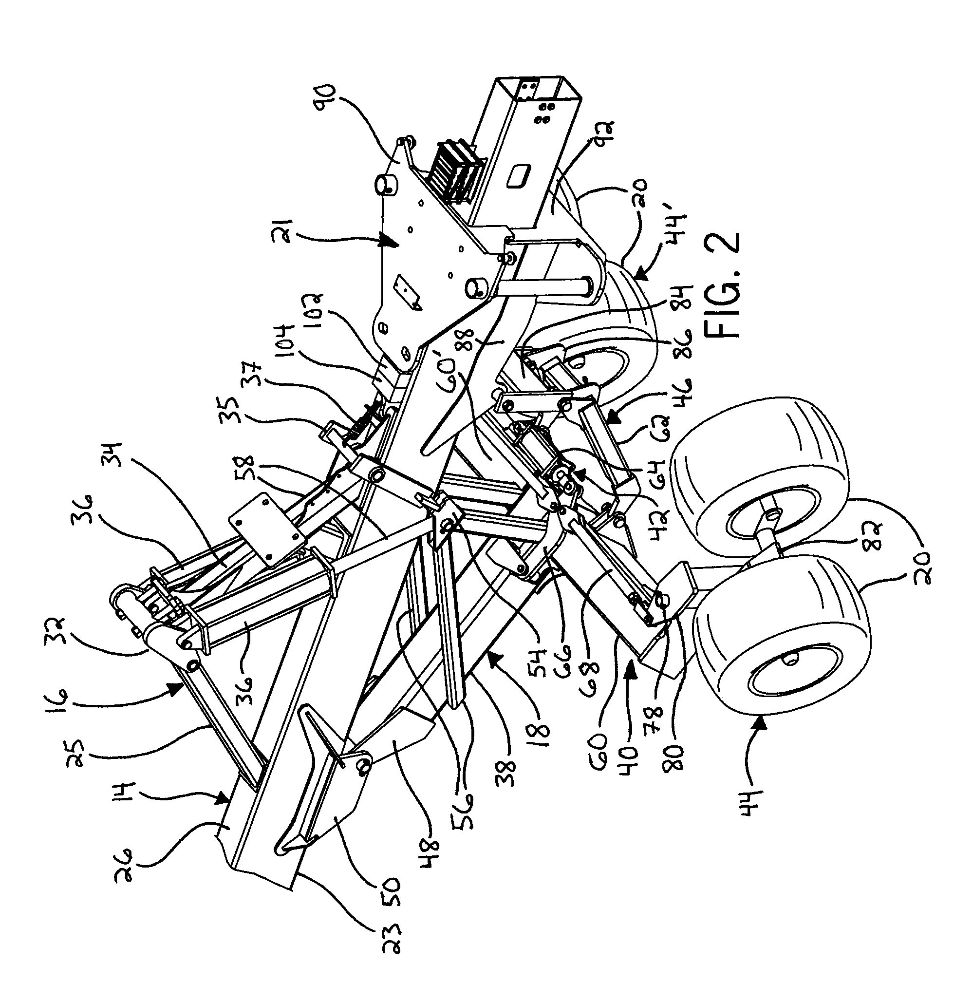
[0044]Referring now to the drawings wherein like reference numerals correspond to similar elements throughout the several views, and more specifically referring to FIGS. 1-12, an embodiment of the invention will be described in the context of a work vehicle 96 (FIG. 9), such as a tractor, which is linked to an agricultural implement 10 by an extendable hitch 12 and a connection joint 13. In this description, the word ‘linked’ should be understood as a connection between components in which the components can rotate relative to one another. In addition to the extendable hitch 12, the agricultural implement 10 includes a frame 14, a lift cylinder anchor member 16 that connects to and supports hydraulic cylinders 36, a wheel support member 18 that connects to wheel pivot assemblies 44 and 44′, a boom support member 21 that supports foldable wing booms 22 and 24, and a positioning system 100 that steers the wheel pivot assemblies 44 and 44′. Referring to FIG. 1, the foldable wing booms ...


PUM


Abstract

An assembly for facilitating steering of an agricultural implement linkable to a work vehicle is disclosed. The assembly comprises at least a first ground-engaging wheel to engage a ground surface below a frame of the agricultural implement to support the frame above the ground surface. The assembly further comprises a positioning system for receiving a positioning signal from a positioning source. The positioning system determines a current position of the agricultural implement from at least the positioning signal, and the positioning system generates a control signal derived from the current position of the agricultural implement. The assembly further comprises a steering cylinder connected to the first ground-engaging wheel. The steering cylinder operatively connects to the positioning system to steer the first ground-engaging wheel based on the control signal.

Description

CROSS-REFERENCE TO RELATED APPLICATIONS[0001]This application is a continuation-in-part of U.S. patent application Ser. No. 12 / 113,674, filed on May 1, 2008, which is hereby incorporated by reference as if fully set forth herein.STATEMENT REGARDING FEDERALLY SPONSORED RESEARCH OR DEVELOPMENT[0002]Not applicable.BACKGROUND OF THE INVENTION[0003]The present invention relates to lift and steering mechanisms for agricultural implements and more specifically to an assembly that can automatically adjust the height of an implement main frame and to steer implement wheels.[0004]Large agricultural planters typically include a central frame assembly that is supported by a plurality of ground engaging wheels, one or more long tool supporting booms or wing frame assemblies mounted to the central frame assembly and extending laterally there from to, as the label implies, support planter row units, and a hitch that extends in a forward direction from the frame to link the planter to a tractor or ...

Claims


Application Information

Patent Timeline
IPC IPC(8): A01B69/00
CPCA01B69/004A01B69/003
Inventor THOMPSON, DENNISFRIGGSTAD, TERRY
Owner CNH IND CANADA
Learn More