Systems and methods for safe laser imaging, detection and ranging (LIDAR) operation

a laser imaging and detection and range technology, applied in the field of safe laser imaging, detection and range (lidar) operation, can solve the problems of people on the ground being exposed to this hazard, the intensity of lasers used,

Inactive Publication Date: 2009-11-05
HONEYWELL INT INC
View PDF9 Cites 287 Cited by
  • Summary
  • Abstract
  • Description
  • Claims
  • Application Information

AI Technical Summary

Benefits of technology

[0003]The present invention provides a Laser Imaging, Detection and Ranging (LIDAR) or Laser Radar (

Problems solved by technology

One potential problem with LIDAR systems relates to the intensity of the lasers used.
While an aircraft is o

Method used


Image

  • Systems and methods for safe laser imaging, detection and ranging (LIDAR) operation
  • Systems and methods for safe laser imaging, detection and ranging (LIDAR) operation
  • Systems and methods for safe laser imaging, detection and ranging (LIDAR) operation

Examples


Embodiment Construction

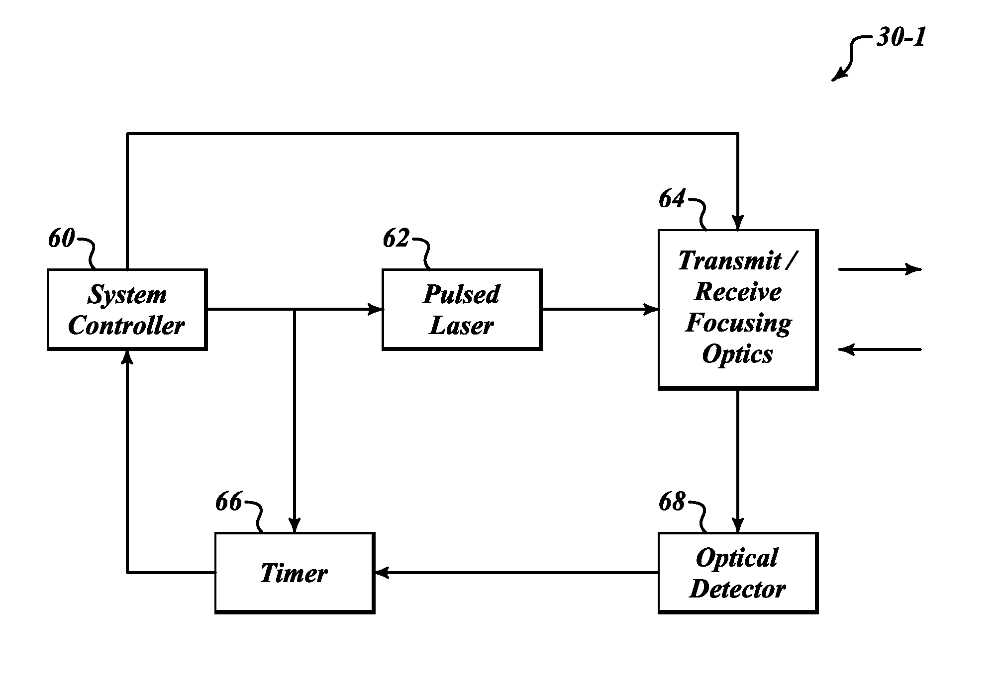
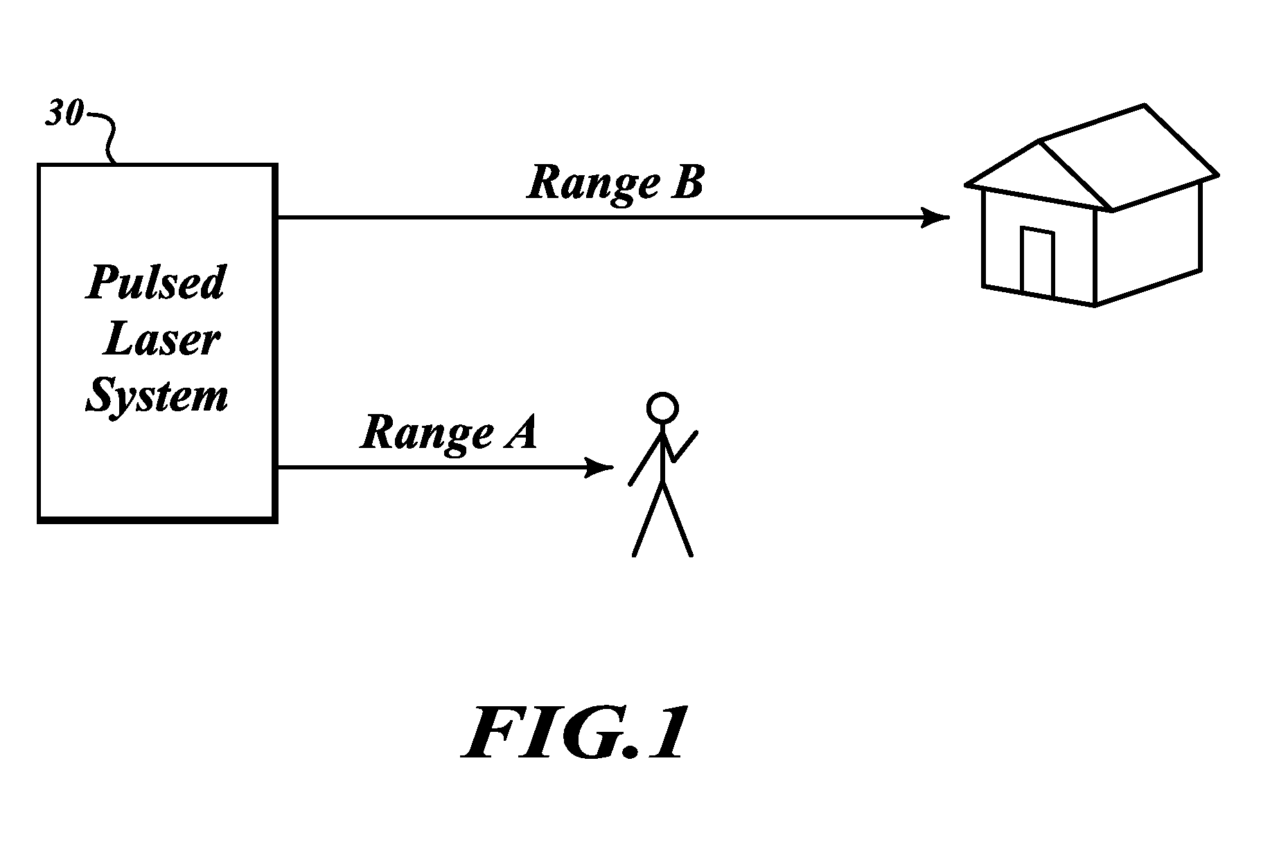
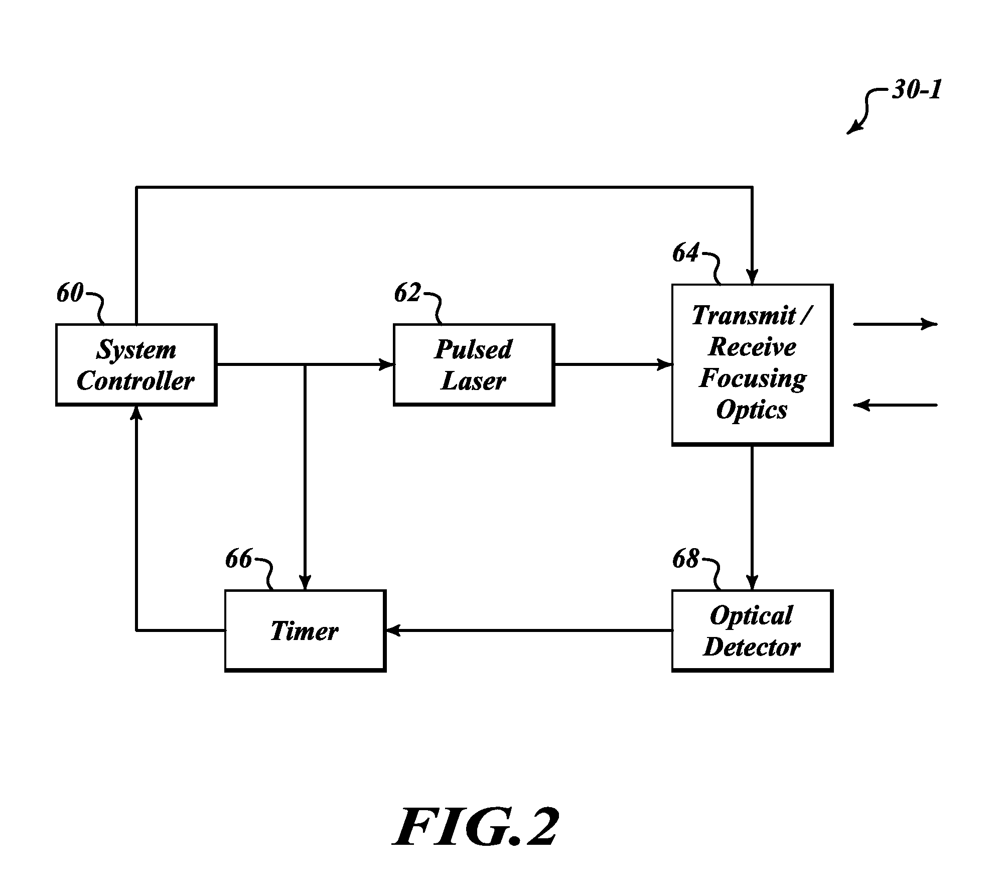
[0014]FIG. 1 illustrates an example laser system 30 that performs automatic range sensing and adjustment of an outputted laser beam (pulse) in order to reduce the eye hazard caused by the outputted laser beam. The system 30 is a pulsed laser system, such as a Laser Imaging Detection and Ranging (LIDAR) or Laser Detection and Ranging (LADAR) system.

[0015]The laser system 30 is initially set to optimize return signals at a first desired range, Range B. Range B is selected based on approximate distance to objects that the operator is expecting to detect targets. The power of the laser system 30 is optimized to produce the most accurate results for detecting targets at Range B. The power setting for the laser system 30 is set such that if there was a human at Range B the power and intensity of the outputted laser beam would not cause any significant eye, skin or other damage to that person. However, within a distance (Range A) less than Range B the laser system 30 would be hazardous to ...


PUM


Abstract

A Laser Imaging, Detection and Ranging (LIDAR) system that automatically adjusts laser output so that no eye damage occurs to human targets. In one example, a component automatically measures range to targets in a field of view and determines the closest targets based on the measured range. A laser device outputs a laser beam and a controller adjusts one of pulse repetition frequency, power, or pulse duration of the laser device based on the measured range of the closest target in order to comply with a predefined eye safety model.

Description

BACKGROUND OF THE INVENTION[0001]Laser Imaging, Detection and Ranging (LIDAR) systems are measuring systems that detect and locate objects using the same principles as radar, but use light from a laser. LIDAR systems can be used on aircraft, for example, for a number of purposes. One example of a LIDAR system on an aircraft is an altimeter which uses laser range finding to identify a height of the aircraft above the ground. Another example of a LIDAR system on an aircraft could include a system which detects air turbulence. Other uses on aircraft are possible, for example including on-ground range finding for purposes of on-ground navigation of aircraft in proximity to airports, etc. Non-aircraft uses of LIDAR systems are also possible.[0002]One potential problem with LIDAR systems relates to the intensity of the lasers used. While an aircraft is on the ground or flying at low airspeeds and altitude, people on the ground could be exposed to this hazard.SUMMARY[0003]The present inven...

Claims


Application Information

Patent Timeline
IPC IPC(8): G01C3/08
CPCG01C3/08G01S7/4802G01S17/10G01S17/023G01S7/497G01S17/86
Inventor BAUHAHN, PAUL E.FRITZ, BERNARD S.KRAFTHEFER, BRIAN C.
Owner HONEYWELL INT INC
Why Eureka
Try Eureka