
Back brace for spinal correction and its manufacturing method

a back brace and spinal technology, applied in the field of back brace for spinal correction, can solve the problems of inability to really achieve a correction, prone to make a wearer feel uncomfortable, and may again get worse, so as to achieve effective scoliosis correction, not make a wearer look clumsy, and reduce the risk of back muscle atrophy

Inactive Publication Date: 2009-11-05
LIU GERALD
View PDF7 Cites 56 Cited by
  • Summary
  • Abstract
  • Description
  • Claims
  • Application Information

AI Technical Summary

Benefits of technology

[0011]The object of this invention is to offer a back brace for spinal correction and its manufacturing method. The back brace can be worn quickly, and will not make a wearer look clumsy and cause atrophy of the back muscles. Especially, a patient who has a curved angle more than 40 degrees, conventionally needing a surgery to correct it, can wear the back brace to positively achieve an effective correction for scoliosis and reverse rotation of the spine.

Problems solved by technology

According to Cobb angle, a scoliosis curve less than 20 degrees usually means that nothing needs to be done except for regular checkups and rehabilitation; if the curve is 20 to 40 degrees, except rehabilitation, to wear a back brace is generally suggested; as for a curve larger than 40 degrees, surgery is necessary because rehabilitation and wearing a back brace does not work effectively.
However, as surgery is supposed to be risky and involve sequelae, it is always the last choice for a spinal correction.
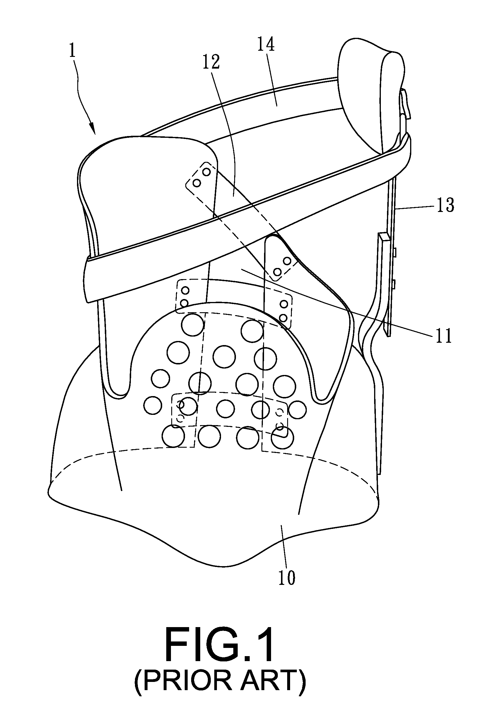
1. The conventional back brace 1 can only function to fix and support the spine so as to prevent the spine from continuing to further curve; once it is taken off a patient, curvature of the spine may again get worse, unable to really achieve a correction.
2. As a standard wearing time of the back brace 1 has to last 23 hours each day, it is prone to make a wearer feel uncomfortable.
4. The back brace 1 is only suitable for correcting a deformed angle less than 40 degrees, with no capability of correcting spinal rotation.

Method used


Image

  • Back brace for spinal correction and its manufacturing method
  • Back brace for spinal correction and its manufacturing method
  • Back brace for spinal correction and its manufacturing method

Examples


Embodiment Construction

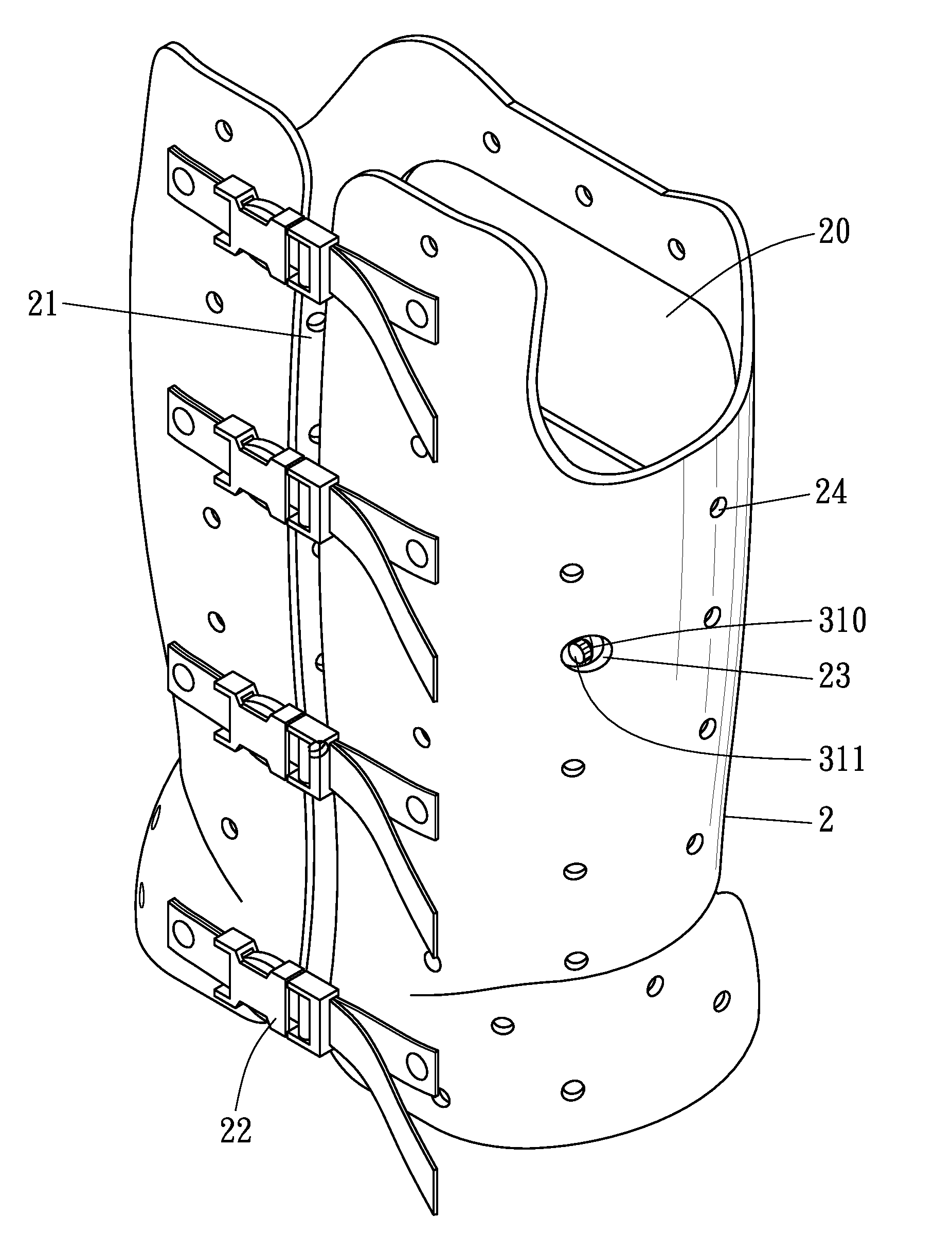
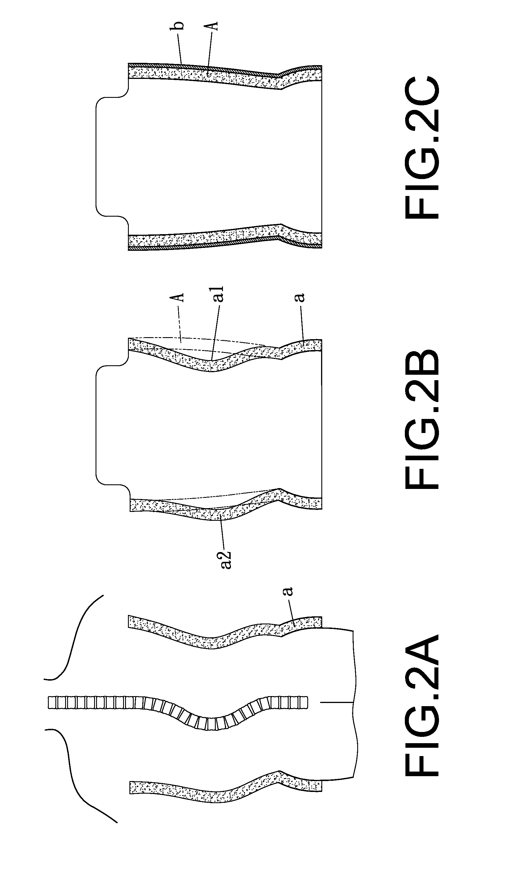
[0030]FIGS. 2˜6 show a preferred embodiment of a back brace and its manufacturing method for spinal correction in the present invention. The back brace is composed of a correction brace 2, at least an air bag 3 and at least a protection cushion 4. Before making the correction brace 2, a patient's spine is previously photoed by X-ray to identify its deformity. Then, as shown in FIG. 2A, an original gypseous model (a) is made according to a patient's shape with a curvature. Next, as shown in FIG. 2B, the original gypseous model (a) is amended to become a revised model (A) in a normal shape, with a recessed portion (a1) filled with gypsum and with a humped portion (a2) cut off. The revised model (A) is successively wrapped with a heated thermoplastic board (b), as shown in FIG. 2C. The thermoplastic board (b) is the correction brace 2 after cooled down. The correction brace 2 is provided with a big through hole 20 bored at its front side for corresponding to a user's chest, an vertical...


PUM


Abstract

The invention relates to a back brace for spinal correction and its manufacturing method. A correction brace is made according to a patient's shape, having its inside installed with plural air bags corresponding to a deformed portion and locations of reverse spinal rotation. Each air bag has an inflation valve fitted in a small through hole bored in the correction brace for a professional to inflate or deflate it to adjust pressure, laid with a soft protection cushion. An effective correction of scoliosis and reverse rotation of the vertebra can be achieved by the air bags correspondingly installed inside the correction brace to force a spinal deformed portion in three dimensions.

Description

BACKGROUND OF THE INVENTION[0001]1. Field of the Invention[0002]This invention relates to a back brace for spinal correction and its manufacturing method, particularly to one provided with air bags fixed inside a correction brace, able to correct serious scoliosis and rotation of a vertebra of a spine by coupling with other medical treatments.[0003]2. Description of the Prior Art[0004]Usually, if a human being has scoliosis or other spinal deformities, he / she should be diagnosed and treated by experts, coupled with rehabilitation treatment to keep his / her spine normally re-positioned. According to Cobb angle, a scoliosis curve less than 20 degrees usually means that nothing needs to be done except for regular checkups and rehabilitation; if the curve is 20 to 40 degrees, except rehabilitation, to wear a back brace is generally suggested; as for a curve larger than 40 degrees, surgery is necessary because rehabilitation and wearing a back brace does not work effectively. However, as ...

Claims


Application Information

Patent Timeline
IPC IPC(8): A61F5/00
CPCA61F5/34A61F5/022
Inventor LIU, GERALD
Owner LIU GERALD
Learn More