Hologram recorder

Inactive Publication Date: 2009-11-12
FUJITSU LTD
View PDF2 Cites 0 Cited by
  • Summary
  • Abstract
  • Description
  • Claims
  • Application Information

AI Technical Summary

Benefits of technology

[0006]The present invention has been proposed under the circumstances described above. It is, therefore, an object of the present invention to provid

Problems solved by technology

This leads to optical deterioration of reproduction signals and is disadvantageous for the enhancement of multiplicity in multiple

Method used


Image

  • Hologram recorder
  • Hologram recorder
  • Hologram recorder

Examples


Example

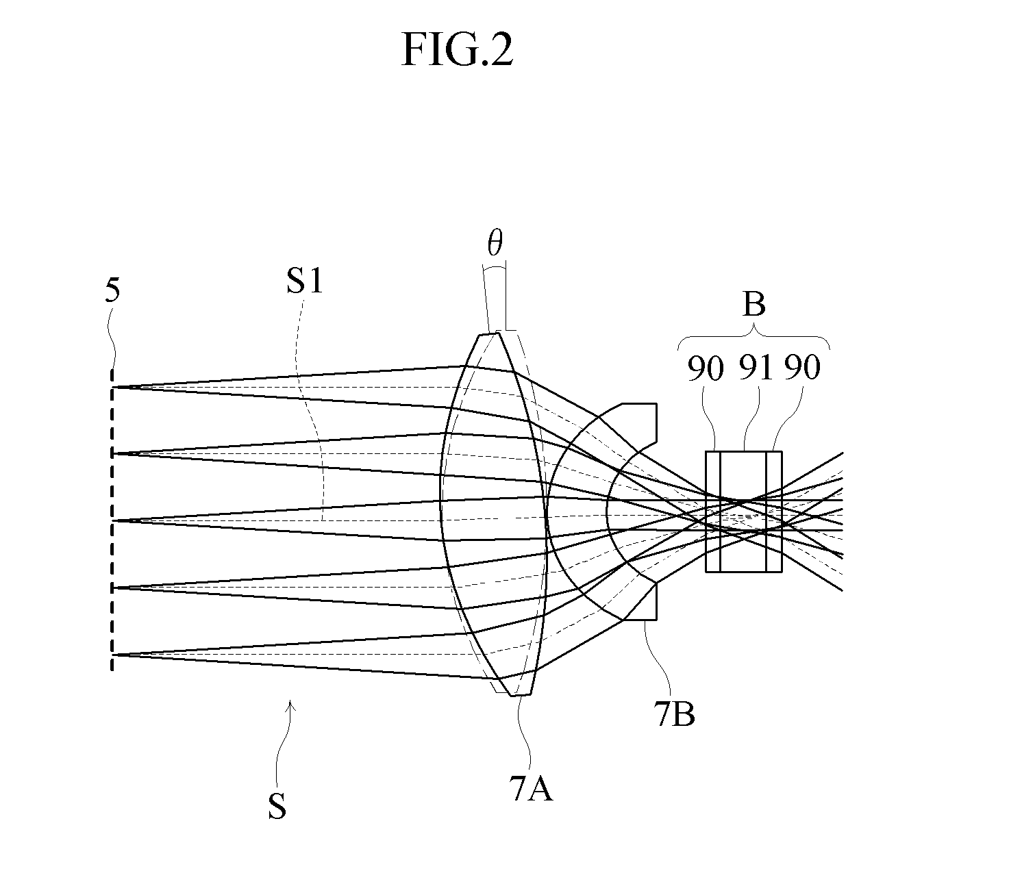
[0019]Preferred embodiments of the present invention will be described below with reference to the accompanying drawings. FIGS. 1-3 illustrate a hologram recording apparatus according to a first embodiment of the present invention.

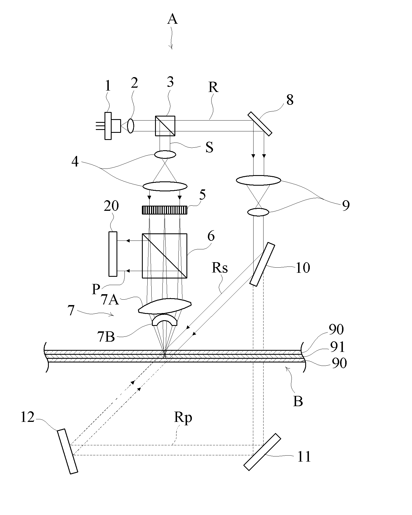
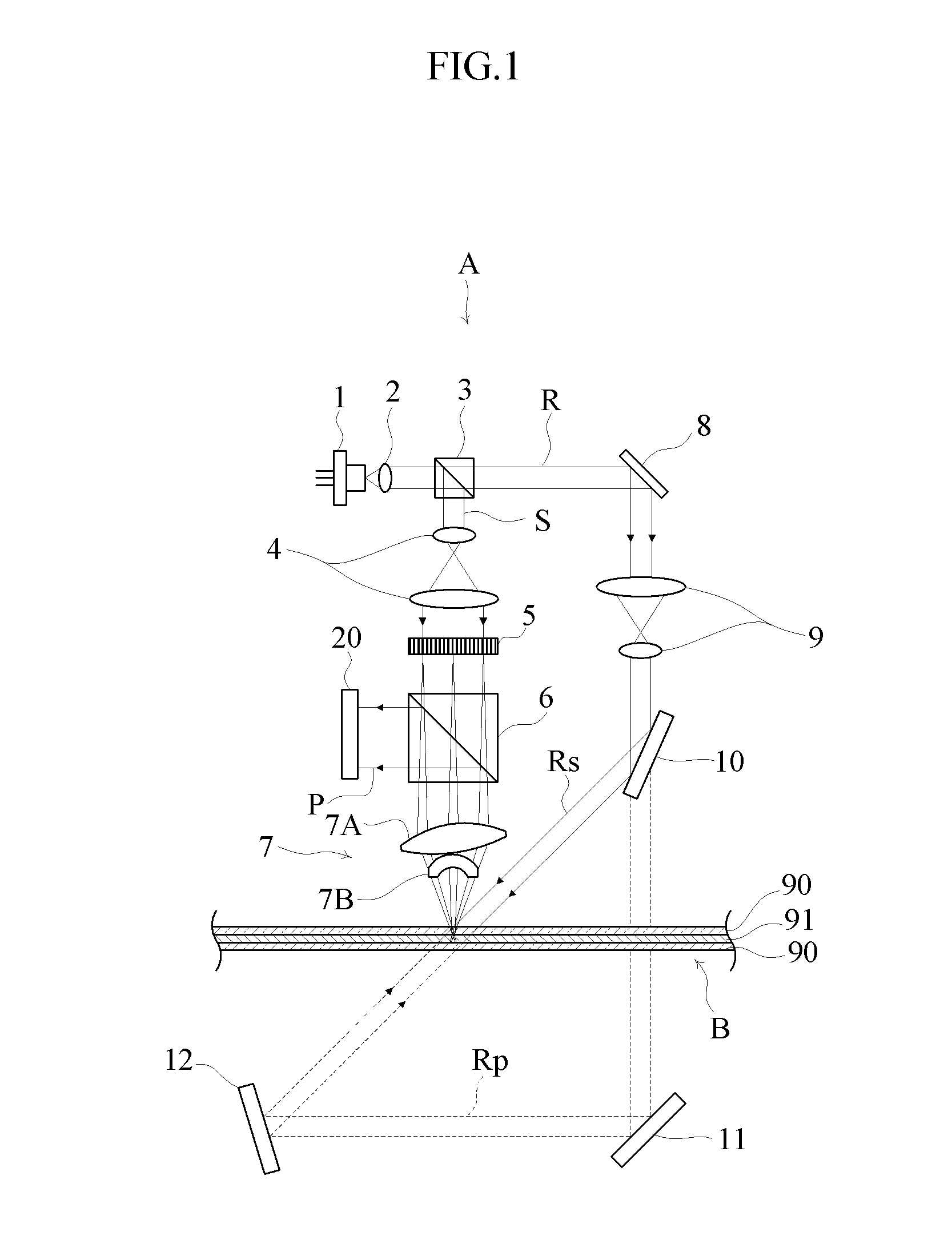
[0020]As illustrated in FIG. 1, the hologram recording apparatus A is designed to record holograms by illuminating a hologram recording medium B with a recording beam S in such a manner as to overlap a recording reference beam Rs. In the reproducing process, a reproducing reference beam Rp as phase conjugate light for the recording reference beam Rs is directed to the hologram recording medium B. The holograms are reproduced by receiving the reproduction beam P produced by diffraction.

[0021]The hologram recording apparatus A includes a light source 1, a collimating lens 2, a beam splitter 3, a recording zoom lens 4, a spatial light modulator 5, a half mirror 6, an objective lens 7 to which the present invention is applied, a first reflector 8, a reference ...


PUM


Abstract

A hologram recording apparatus includes an objective lens (7) for illuminating a hologram recording medium (B) with a recording beam (S) in a manner such that the recording beam overlaps a reference beam, thereby performing multiple recording of holograms at a portion illuminated with the reference beam and the recording beam (S). The objective lens (7) includes at least one rotationally symmetric lens (7A, 7B), and at least one rotationally symmetric lens (7A) is so arranged that the lens optical axis is inclined with respect to the direction (S1) in which the recording beam (S) travels.

Description

TECHNICAL FIELD[0001]This application is a Continuation based on International Application No. PCT / JP2007 / 055209.[0002]The present invention relates to a hologram recording apparatus including an objective lens for illuminating a hologram recording medium with a recording beam.BACKGROUND ART[0003]An example of conventional hologram recording apparatus is disclosed in Patent Document 1. The hologram recording apparatus disclosed in this document includes an objective lens for illuminating a hologram recording medium with a recording beam and a reference beam by so-called collinear holography. The focusing performance of an objective lens can be enhanced by increasing the numerical aperture (NA). However, when the focusing performance is enhanced, the recording material of a recording layer is consumed locally at the portion onto which the light is focused. This leads to optical deterioration of reproduction signals and is disadvantageous for the enhancement of multiplicity in multipl...

Claims


Application Information

Patent Timeline
IPC IPC(8): G03H1/26G11B7/135
CPCG03H1/0402G03H1/16G11B2007/13727G11B7/083G11B7/1374G03H2001/0413
Inventor YAMAKAGE, YUZURUUNO, KAZUSHIYOSHIKAWA, HIROYASU
Owner FUJITSU LTD
Why Eureka
Try Eureka