

Magneto-resistive device, and magnetic head, head suspension assembly and magnetic disk apparatus using magneto-resistive device
- Summary
- Abstract
- Description
- Claims
- Application Information
AI Technical Summary
Benefits of technology
Problems solved by technology
Method used
Image

Examples
first embodiment
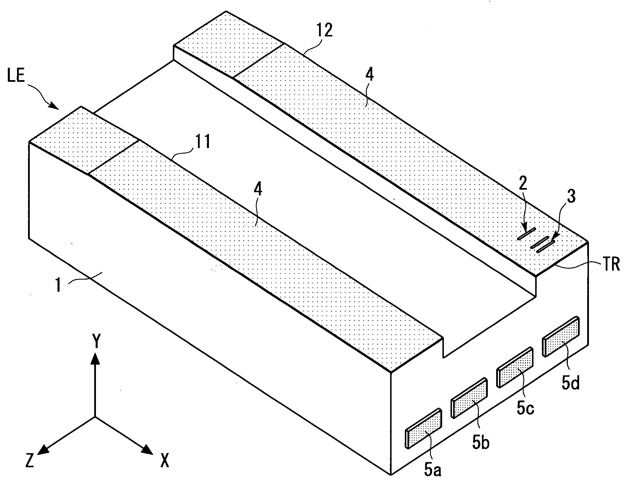
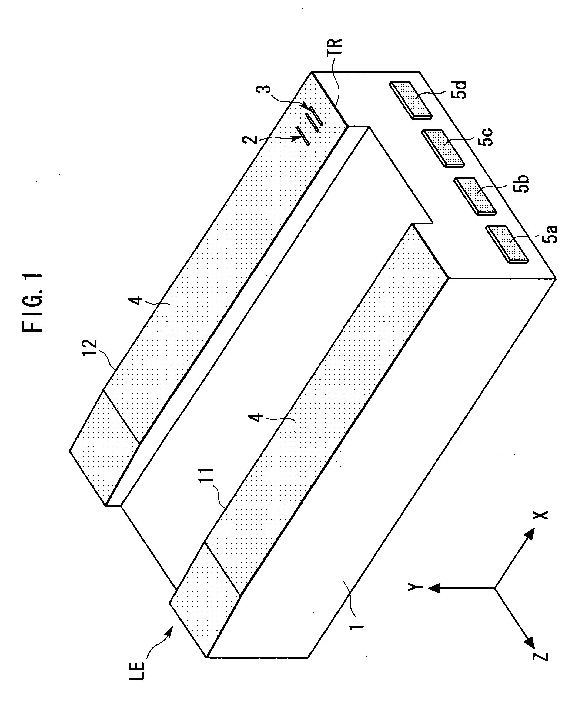
[0067] First, a magnetic head according to the present invention will be described with reference FIGS. 1 to 5.
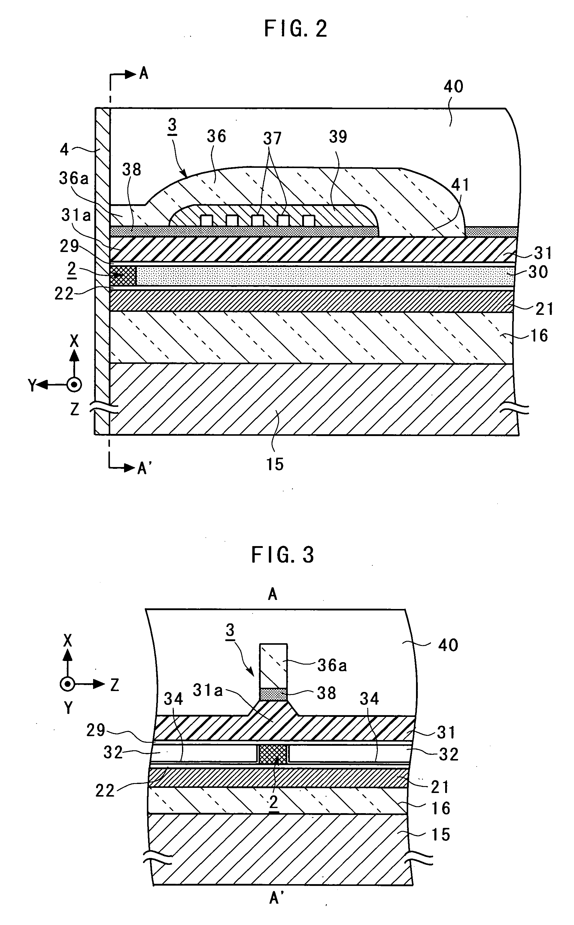
[0068]FIG. 1 is a general perspective view schematically illustrating the magnetic head according to the first embodiment of the present invention. FIG. 2 is an enlarged cross-sectional view schematically illustrating a portion of a TMR device 2 and an inductive magnetic transducing device 3 in the magnetic head illustrated in FIG. 1. FIG. 3 is a general sectional view taken along a line A-A′ indicated by arrows in FIG. 2. FIG. 4 is a further enlarged view illustrating around the TMR device 2 in FIG. 2. FIG. 5 is a further enlarged view around the TMR device 2 in FIG. 3. For facilitating the understanding, an X-axis, a Y-axis and a Z-axis, orthogonal to one another, are defined as shown in FIG. 1 to 5 (the same applies to figures later described). The Z-axis direction indicated by the arrow is referred to as the “+Z-direction” or “+Z-side,” and the opposite direction is ref...
second embodiment
[0099] Next, a magnetic head according to the present invention will be described with reference to FIGS. 10 to 12.
[0100]FIG. 10 is an enlarged cross-sectional view schematically illustrating a portion of a GMR device 50 and an inductive magnetic transducing device 3 in a magnetic head according to a second embodiment of the present invention. FIG. 11 is a general sectional view taken along a line B-B′ indicated by arrows in FIG. 10. FIG. 12 is a further enlarged view illustrating around the GMR device 50 in FIG. 11. FIGS. 10 to 12 correspond to FIGS. 2, 3 and 5, respectively. In FIGS. 10 to 12, components identical or corresponding to those in FIGS. 1 to 5 are designated by the same reference numerals, and repeated description thereon is omitted.
[0101] The magnetic head according to the second embodiment is basically similar to the magnetic head disclosed in JP-A-2003-60262 in that it is implemented by a CPP-GMR head having a magneto-resistive layer which includes a thin insulatin...
third embodiment
[0109] Next, a magnetic disk apparatus according to the present invention will be described with reference to FIG. 13.
[0110]FIG. 13 is a perspective view generally illustrating the configuration of a main portion of a magnetic disk apparatus according to a third embodiment of the present invention.
[0111] The magnetic disk apparatus according to the third embodiment comprises magnetic disks 71 rotatably mounted about a shaft 70; magnetic heads 72 each for recording and reproducing information to or from associated one of the magnetic disks 71; and an assembly carriage device 73 for positioning the magnetic head 72 on a track of the magnetic disk 71.
[0112] The assembly carriage device 73 mainly comprises a carriage 75 mounted for pivotal movements about a shaft 74; and an actuator 76 comprised, for example, of a voice coil motor (VCM) for rotating the carriage 75.
[0113] The carriage 75 is mounted with bases of a plurality of driving arms 77 which are stacked in the direction of the...
PUM
| Property | Measurement | Unit |
|---|---|---|
| Electrical conductor | aaaaa | aaaaa |
| Bond energy | aaaaa | aaaaa |
| aaaaa | aaaaa |
Abstract
Description
Claims
Application Information