
Recorder, Player, and Recorder/Player

Inactive Publication Date: 2008-11-20
PANASONIC CORP
View PDF6 Cites 6 Cited by
  • Summary
  • Abstract
  • Description
  • Claims
  • Application Information

AI Technical Summary

Benefits of technology

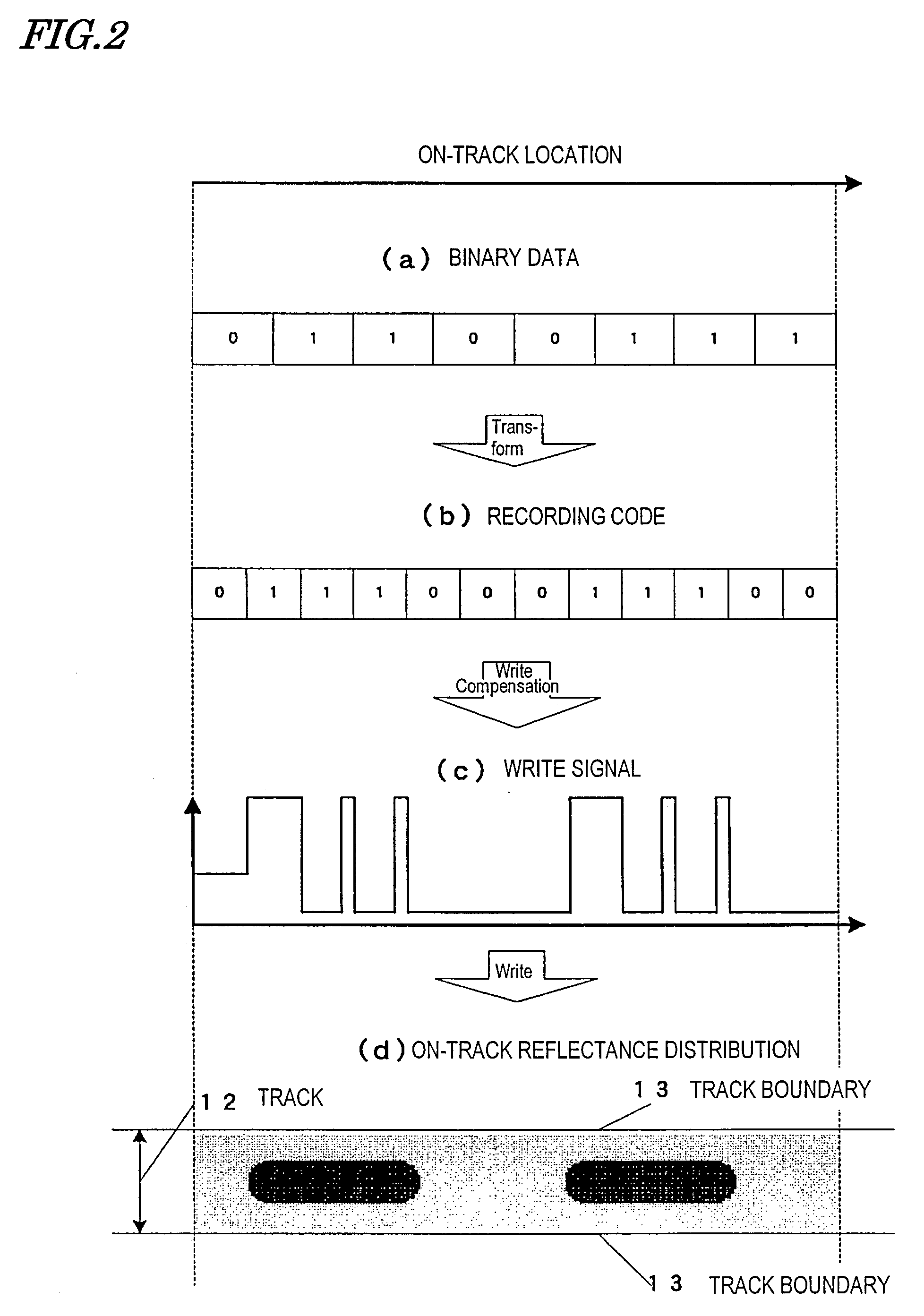
[0054]Paying attention to one particular location on an information storage medium, the information storage medium of the present invention includes a recording layer, which has an optical constant that changes continuously with the integrated quantity of light received at that location. When the recording layer is irradiated with multiple pulsed beams at an interval that is shorter than the diameter of the pulsed beams, a write compensation section generates a write signal such that the sum of variations in the optical constant at each irradiated spot of the pulsed beam on the recording layer through the end of a write operation has a predetermined variation pattern. By using such an information storage medium that has a continuously changing optical constant, information can be written using a multiplexed signal (e.g., an orthogonal frequency division multiplexed signal) and the recording density of the information storage medium can be increased. Also, by generating the write signal such that the sum of variations in the optical constant has a predetermined variation pattern, information can be written on such an information storage medium that has a continuously changing optical constant.
[0055]According to the present invention, a non-run-length-limited code can be used. That is why the error rate never deteriorates due to propagation of errors of a recording code and the errors can also be corrected. As a result, the recording density can be further increased.
[0056]In a preferred embodiment of the present invention, a difference in frequency between carrier signals of respective sub-channel signals is an integral multiple of the product of the inverse number of one symbol length and the linear velocity of the optical disk medium. Thus, the respective sub-channel signals have an orthogonal relation with respect to each other. By superposing those sub-channel signals with each other, a write signal is generated. And following the pattern of such a write signal, the optical constant of the recording layer changes and a write operation is carried out on a symbol-by-symbol basis. That is to say, this write operation is performed without threshold values, i.e., as analog recording.
[0057]In another preferred embodiment of the present invention, information is written on an information storage medium by superposing a number of mutually orthogonal sub-channel signals on a symbol-by-symbol basis. Also, a read signal is generated based on the light that has been reflected from such an information storage medium, and is multiplied by each of carrier signals, thereby generating each of sub-channel signal. Then, the stored information is detected using those sub-channel signals. By reading and writing information by a multiplexing method such as orthogonal frequency division multiplexing in this manner, the recording density of the information storage medium can be increased.
[0058]In still another preferred embodiment of the present invention, when irradiated with a beam, the molecules of the material of the recording layer change their directions perpendicularly (or parallel) to the plane of polarization of the beam, thereby writing information there. When the molecules of the material of the recording layer change their directions, an optical rotatory phenomenon arises, thus changing the refractive index. And when the refractive index changes, the reflectance also changes. Also, the directions of the molecules of the material of the recording layer are proportional to the square of the beam intensity. Furthermore, as there are two optical rotatory directions, two different pieces of information can be written per sub-channel.
[0059]In yet another preferred embodiment of the present invention, the optical constant (such as refractive index) changes due to the two-photon absorption reaction of the material of the recording layer. Therefore, the optical constant is proportional to the square of the intensity of the pulsed beam. That is why even if the recording power has varied for some reason, the influence on the optical constant is proportional to the root of the power variation. That is to say, the influence of the power variation on the optical constant can be reduced. As a result, the recording power margin can be increased and more stabilized recording is realized.

Problems solved by technology

That is to say, the higher the frequency of the recording signal (i.e., the smaller the marks or spaces to be record), the more difficult it is to get the write operation done accurately.

Method used


Image

  • Recorder, Player, and Recorder/Player
  • Recorder, Player, and Recorder/Player
  • Recorder, Player, and Recorder/Player

Examples


Embodiment Construction

[0271]Hereinafter, preferred embodiments of the present invention will be described with reference to the accompanying drawings.

[0272]Portion (a) of FIG. 6 shows the format of an information storage medium according to a preferred embodiment of the present invention, which may be an optical disk medium, for example. The optical disk medium 61 shown in portion (a) of FIG. 6 includes a base material 67a and at least one recording layer 67. The recording layer 67 is arranged on the base material 67a. In the example illustrated in FIG. 6, the optical disk medium 61 includes a plurality of recording layers 67.

[0273]The recording layer 67 is made of a photon mode recording material with almost no threshold value. Also, the recording layer 67 has an optical constant that changes continuously with the total quantity of light received. For example, the variation in the optical constant of the recording material may be substantially a function (e.g., a liner function or a quadratic function) ...


PUM


Abstract

An apparatus according to the present invention includes a write compensation section, which generates a write signal to write information on an information storage medium, and a writing section for irradiating the information storage medium with a pulsed beam based on the write signal generated by the write compensation section. The information storage medium includes a recording layer, which has an optical constant that changes continuously with the total quantity of light received. The writing section radiates and condenses multiple pulsed beams on the recording layer at an interval that is shorter than the diameter of the pulsed beams on the recording layer. The write compensation section generates the write signal such that the each sum of variations in the optical constant at each irradiated spot of the pulsed beam on the recording layer through the end of a write operation forms a predetermined variation pattern.

Description

TECHNICAL FIELD[0001]The present invention relates to an apparatus for reading and / or writing information from / on an information storage medium.BACKGROUND ART[0002]To increase the storage capacity of an optical disk medium, which is one of various types of information storage media, it is effective to increase the numerical aperture of the objective lens and shorten the wavelength of the laser beam. This is because the size of a condensed laser beam spot is inversely proportional to the numerical aperture of an objective lens and directly proportional to the wavelength of the laser beam. That is why if the numerical aperture of the objective lens is increased and if the wavelength of the laser beam is shortened, the size of the condensed laser beam spot can be decreased and read / write operations can be done with marks and spaces of reduced lengths. Such a method of writing information with the mark / space widths varied is called a pulse width modulation (PWM) recording.[0003]Hereinaf...

Claims


Application Information

Patent Timeline
IPC IPC(8): G11B7/00G11B7/24088
CPCB82Y10/00G11B7/00456G11B7/24088G11B7/245G11B20/10194H04L27/2601H04L27/34
Inventor KOBAYASHI, YOSHIHARU
Owner PANASONIC CORP
Learn More