
Image forming apparatus and control method for controlling the same

Active Publication Date: 2009-11-12
RICOH KK
View PDF4 Cites 16 Cited by
  • Summary
  • Abstract
  • Description
  • Claims
  • Application Information

AI Technical Summary

Benefits of technology

[0011]In view of the foregoing, illustrative embodiments of the present invention provide an image forming apparatus capable of reducing waiting time until start of subsequent image formation even when a request for subsequent image formation is received during a shutdown sequence, and a control method for controlling the image forming apparatus.

Problems solved by technology

Further, new image formation cannot be started while the operations are shut down or started up.
Consequently, the request may not be output before the shutdown determination time after previous image formation is completed.
As a result, the printer engine is shut down even during continuous image formation, and start of subsequent image formation based on such image data is delayed for at least the time required to shut down the operations and then restart such operations.

Method used


Image

  • Image forming apparatus and control method for controlling the same
  • Image forming apparatus and control method for controlling the same
  • Image forming apparatus and control method for controlling the same

Examples


Embodiment Construction

[0039]In describing illustrative embodiments illustrated in the drawings, specific terminology is employed for the sake of clarity. However, the disclosure of this patent specification is not intended to be limited to the specific terminology so selected, and it is to be understood that each specific element includes all technical equivalents that operate in a similar manner and achieve a similar result.

[0040]Illustrative embodiments of the present invention are now described below with reference to the accompanying drawings.

[0041]In a later-described comparative example, illustrative embodiment, and exemplary variation, for the sake of simplicity the same reference numerals will be given to identical constituent elements such as parts and materials having the same functions, and redundant descriptions thereof omitted unless otherwise required.

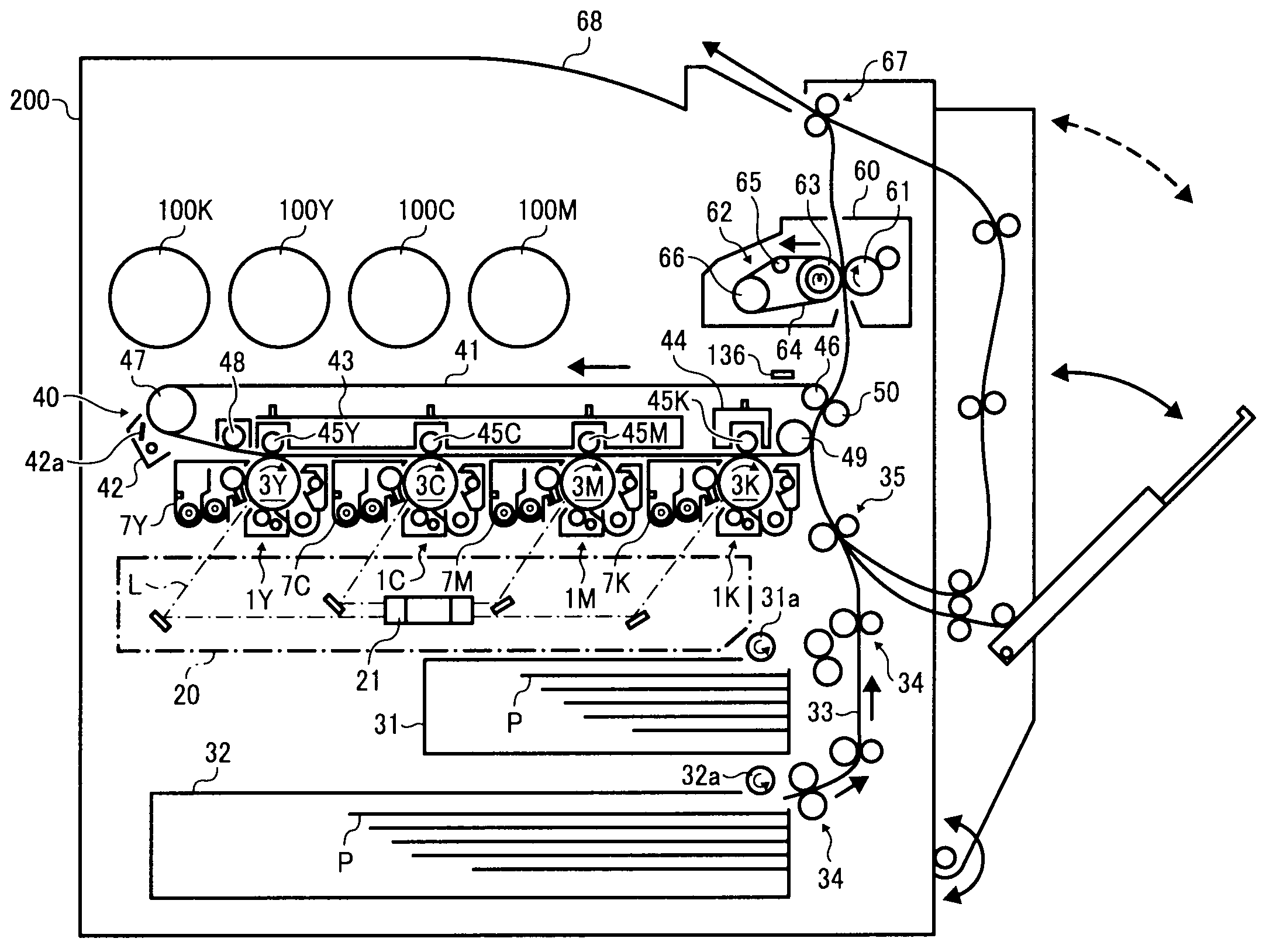
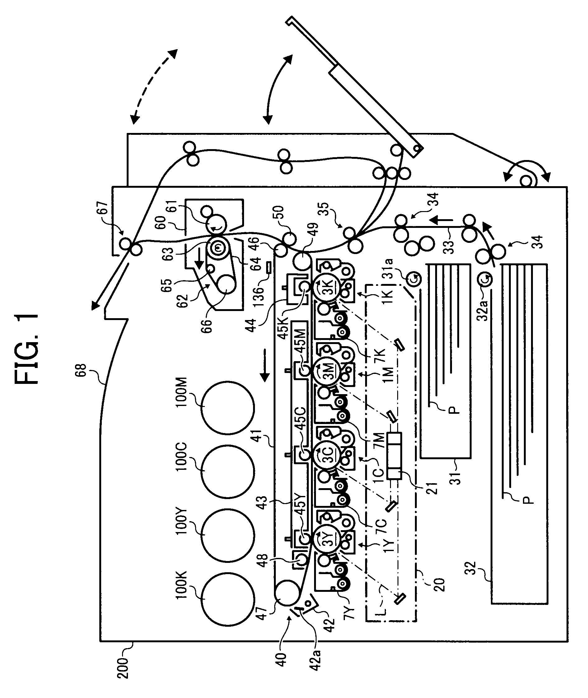
[0042]A description is now given of a printer using an electrophotographic method (hereinafter referred to as an image forming apparatus 200)...


PUM


Abstract

An image forming apparatus including a latent image bearing member a surface of which is rotated, a charging device, an irradiating device, a developing device, a transfer device, and a control unit. The control unit controls the image forming apparatus to perform subsequent image formation in accordance with a subsequent image forming request when determining that the subsequent image forming request is present at a predetermined determination time after completion of previous image formation, and controls the image forming apparatus to shut down certain predetermined operations including at least rotation of the surface of the latent image bearing member and application of a charging bias from the charging device and a developing bias from the developing device in accordance with a predetermined shutdown sequence when determining that the subsequent image forming request is not present at the predetermined determination time.

Description

CROSS-REFERENCE TO RELATED APPLICATIONS[0001]The present patent application is based on and claims priority pursuant to 35 U.S.C. §119 from Japanese Patent Application Nos. 2008-122965, filed on May 9, 2008 in the Japan Patent Office, and 2009-093751, filed on Apr. 8, 2009 in the Japan Patent Office, the entire contents of each of which are incorporated herein by reference.BACKGROUND OF THE INVENTION[0002]1. Field of the Invention[0003]Exemplary aspects of the present invention generally relate to an image forming apparatus such as a copier, a facsimile machine, or a printer that performs image formation by transferring a toner image formed on a surface of an image bearing member onto a recording medium, and a control method for controlling the image forming apparatus.[0004]2. Description of the Background[0005]Related-art image forming apparatuses, such as a copier, a facsimile machine, a printer, or a multifunction printer having two or more of copying, printing, scanning, and fac...

Claims


Application Information

Patent Timeline
IPC IPC(8): G03G15/02
CPCG03G15/50G03G2215/0193G03G2215/0132G03G15/5004
Inventor SHIORI, JUN
Owner RICOH KK
Features
  • Generate Ideas
  • Intellectual Property
  • Life Sciences
  • Materials
  • Tech Scout
  • Unparalleled Data Quality
  • Higher Quality Content
  • 60% Fewer Hallucinations
Learn More