Insertion instrument for joint sockets of prostheses

a technology for insertion instruments and prostheses, which is applied in the field of insertion instruments for joint sockets of prostheses, can solve the problems of affecting the safety of prostheses, so as to achieve the effect of convenient handling and a convenient connection

Active Publication Date: 2009-11-12
KELLER ARNOLD
View PDF11 Cites 31 Cited by
  • Summary
  • Abstract
  • Description
  • Claims
  • Application Information

AI Technical Summary

Benefits of technology

[0006]Starting out from the last-mentioned prior art, the object of the invention is therefore to improve an instrument of the type mentioned at the outset, so as to permit safer and easier handling.

Problems solved by technology

In the latter design, the problem that arises is that, in the case of cementless implantation, the securing requires the component to be hammered in.
This can easily cause damage to the sensitive support insert, particularly if the latter is made of plastic or ceramic material.
The instrument is therefore relatively bulky and awkward to handle specifically under the confined operating conditions.
However, the underpressure is not provided by attachment of an external vacuum source and is instead generated by a pump integrated in the instrument.
The integrated piston pump represents an improvement. over the instrument known from U.S. Pat. No. 3,859,992, but its handling is still relatively complicated.
Moreover, apart from the position of the air valve, the user is given no information on whether or not there is sufficient underpressure in the suction line.

Method used


Image

  • Insertion instrument for joint sockets of prostheses
  • Insertion instrument for joint sockets of prostheses
  • Insertion instrument for joint sockets of prostheses

Examples


Embodiment Construction

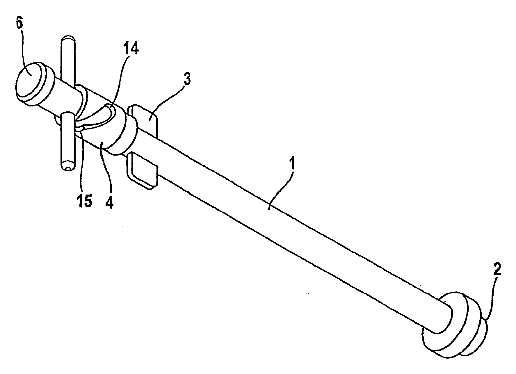
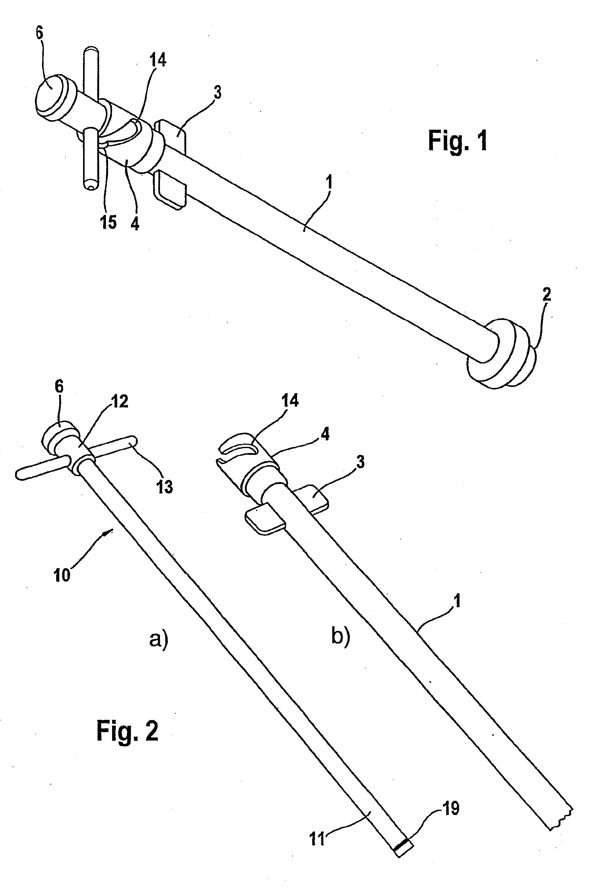
[0022]The instrument according to the invention principally comprises a shaft 1 extending in a cylinder shape. At the front end thereof, a suction head 2 is screwed on replaceably by way of a threaded connection. At the rear end of the shaft 1 there is a pair of wings 3 composed of two diametrically opposite wings that protrude radially outward and form a grip.

[0023]Farther to the rear there is a guide head 4, which can likewise be screwed onto the shaft.

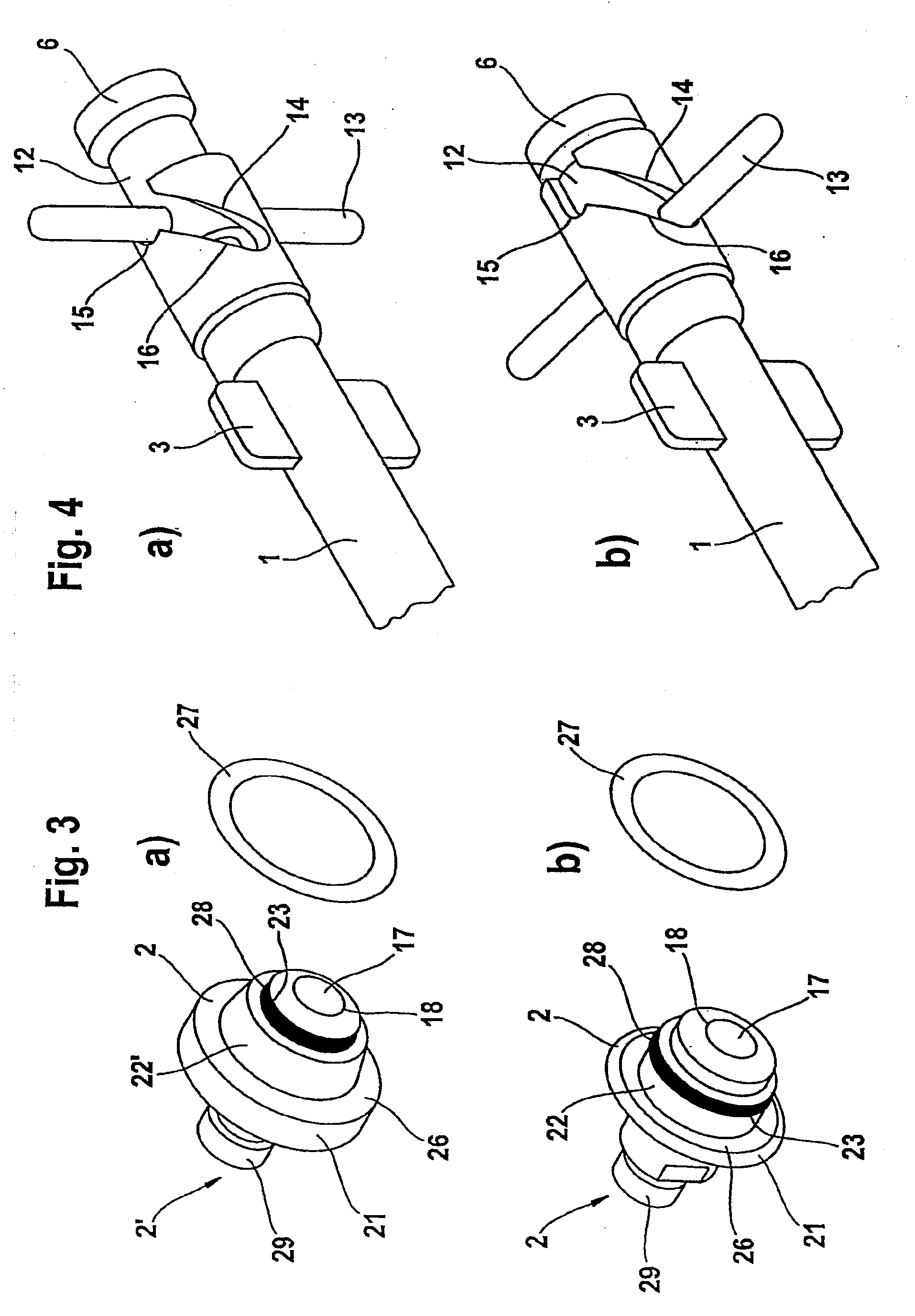
[0024]The shaft 1 is formed as a hollow body and has a cylindrical cavity (not shown). It is a component part of a suction device 10, which is explained in more detail below. The cavity is connected to the tip of the suction head 2 via a suction channel 17 in the suction head 2. The suction channel 17 ends there with a mouth 18. The suction head 2 also has, as main component, a abutment collar 21 and a cylindrically shaped extension 22 with a circumferential groove 23. The abutment collar, with its rear surface directed toward the s...


PUM


Abstract

An insertion instrument comprising an elongate shaft, a suction head provided at the front end thereof for connection to a joint socket, a suction device with a piston guided in the shaft, a suction line opening out at the suction head, and an actuating element which is guided along a guiding track on the shaft. The guiding track can be helically shaped and have a locking arrangement, preferably in the form of a recess, for the actuating element in a suction position. Due to the helical shape of the guiding track, the actuating element executes a rotational and longitudinal movement during its displacement. The longitudinal movement produces a negative pressure in the suction line ensuring maintenance of the pressure, while the rotating movement causes rotation of the actuating element such that it reaches its locking position at the end of the guiding track, providing simplified handling of the instrument.

Description

REFERENCE TO RELATED APPLICATIONS[0001]This application is a national stage application under 35 USC 371 of International Application No. PCT / EP2007 / 005647, filed Jun. 26, 2007, which claims the priority of German Patent Application No. 20 2006 010 069.5, filed Jun. 28, 2006, the contents of which are incorporated herein by reference in their entirety.FIELD OF THE INVENTION[0002]The invention relates to an insertion instrument for joint sockets of prostheses, with an elongate shaft, a suction head provided at the front end thereof for connection to the joint socket, and, furthermore, a suction device with a piston guided in the shaft, a suction line opening out at the suction head, and an actuating element which is guided along a guide track on the shaft.BACKGROUND OF THE INVENTION[0003]Prostheses for certain joints of the human body, in particular for shoulder joints and hip joints, generally comprise a component designed as a joint socket. In a hip prosthesis, this is usually the ...

Claims


Application Information

Patent Timeline
Patent Type & Authority Applications(United States)
IPC IPC(8): A61B17/58
CPCA61F2/4609A61F2002/4685A61F2002/4681A61F2002/30601A61F2/32A61F2/46
Inventor KELLER, ARNOLD
Owner KELLER ARNOLD
Why Eureka
Try Eureka