Portable lock with electronic lock actuator

a technology of electronic lock actuator and portability, which is applied in the field of portability locks, can solve the problems of inability to open these locks, inability to change the method by which these locks are operated, and small locking pins in bacons are unsuitable for securing a shackle in a padlock

Active Publication Date: 2009-11-19
SCHLAGE LOCK
View PDF19 Cites 83 Cited by
  • Summary
  • Abstract
  • Description
  • Claims
  • Application Information

AI Technical Summary

Benefits of technology

[0015]In one aspect, the present invention provides a lock assembly comprising a lock body, a locking member moveable relative to the lock body, and a locking mechanism within the lock body and configured to selectively engage the locking member to prevent movement of the locking member relative to the lock body. An actuating mechanism is associated with locking mechanism and is moveable between an unlocked positioned wherein the locking mechanism is disengageable from the locking member and a locked position wherein the locking mechanism is maintained in engagement with the locking member. An electronic actuator is associated with the actuating mechanism and is configured to selectively move the actuating mechanism between the locked and unlocked positions. A key actuated cylinder is associated with the actuating mechanism and is configured to selectively move the actuating mechanism between the locked and unlocked positions independent of the electronic actuator.
[0016]In another aspect, the present invention provides a lock assembly comprising a lock body, a locking member moveable relative to the lock body, and a locking mechanism within the lock body and configured to selectively engage the locking member to prevent movement of the locking member relative to the lock body. An actuating mechanism is associated with locking mechanism and is moveable between an unlocked positioned wherein the locking mechanism is disengageable from the locking member and a locked position wherein the locking mechanism is maintained in engagement with the locking member. An electronic actuator is associated with the actuating mechanism and is configured to selectively move the actuating mechanism between the locked and unlocked positions. An electrical assembly is configured to receive an unlock signal and associated identification indicia along therewith.

Problems solved by technology

However, unless the user has the key or is able to remember the factory-provided combination, it is not possible to open these locks.
Further, it is not possible to change the method by which these locks may be opened.
Unfortunately, the mechanical linkage of the motor to the tumbler mechanism requires a bulky housing, which is suitable for a door lockset but unsuitable for a padlock, and the small locking pin in Bacon is unsuitable for securing a shackle in a padlock.
This two-stage procedure saves battery life by reducing power consumption, but is thus unsuitable for a lock with a one-stage unlocking procedure.
While the lock in Chang is suitable for a large gearshift lock having an external power source, it is unsuitable for a small padlock requiring a self-contained power supply.
Further, the lock in Chang requires the use of a key, and cannot be operated by simply entering a combination or key-code.
While Babler is well suited to the needs of real estate agents, the lock box in Babler is not suitable for use as a simple Us padlock as the power supply and electronic key are not self-contained within the lock box.
Furthermore, the combination of the lock box is not programmable within a self-contained unit.
This is disadvantageous, because a large spring would require a larger motor and self-contained power supply in order to operate the lock.
Deighton also incorporates an infrared key and lock actuation system, which is disadvantageous as the key could be lost.
Symons has the same disadvantages as other prior art, namely that a spring of sufficient size must be used to ensure the rods securely engage the shackle, thereby necessitating a sufficiently large solenoid and power supply to overcome the force of the springs.
Unfortunately, the use of a spring necessitates a sufficiently sized power supply and solenoid to overcome the force of the spring.
Further, due to the constraints of batteries, this padlock is not suitable to a key-less, self-contained padlock having a long battery life between battery changes.

Method used


Image

  • Portable lock with electronic lock actuator
  • Portable lock with electronic lock actuator
  • Portable lock with electronic lock actuator

Examples


Embodiment Construction

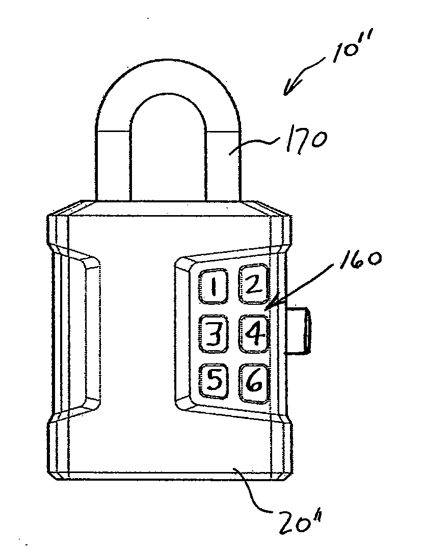
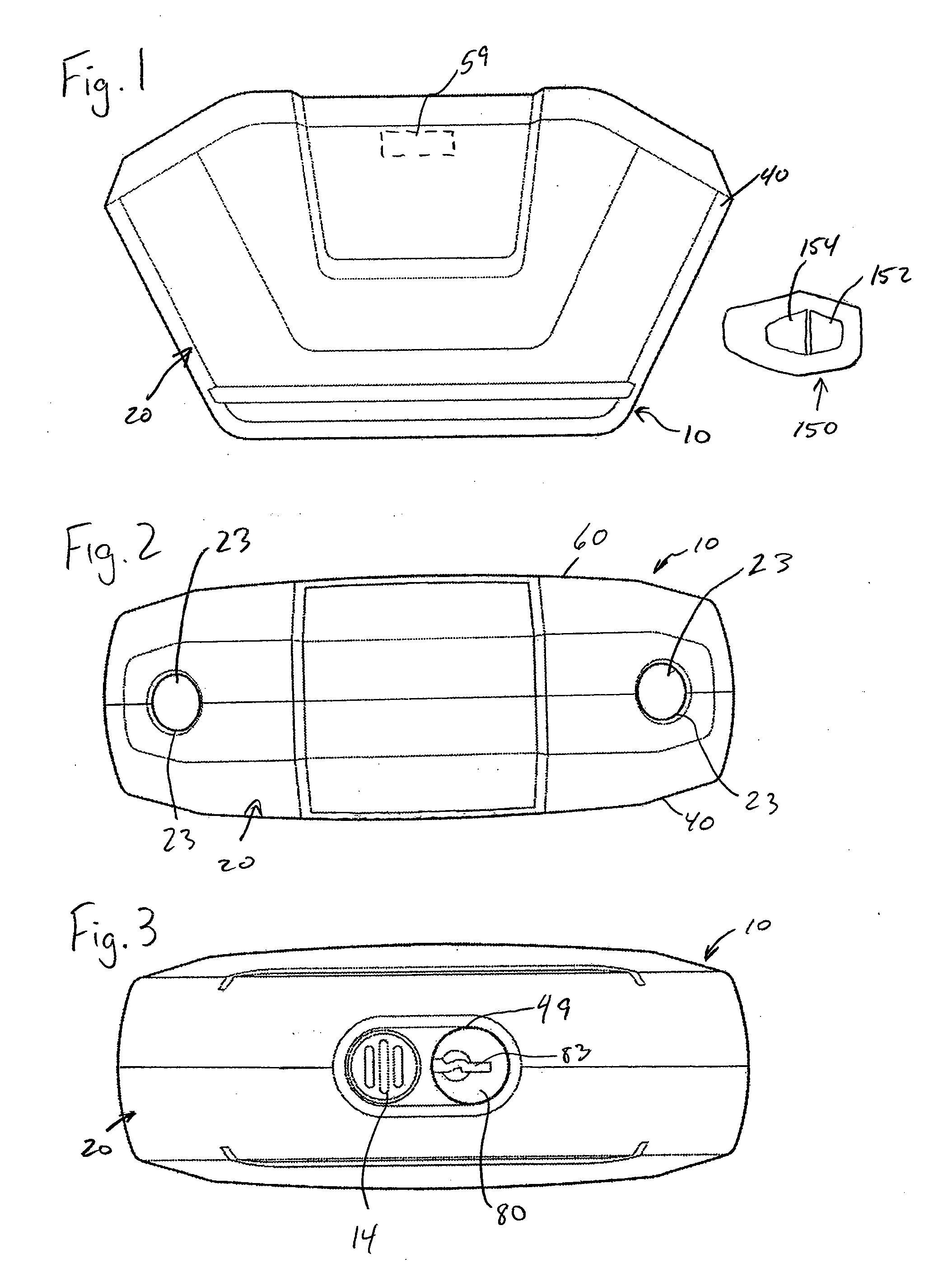
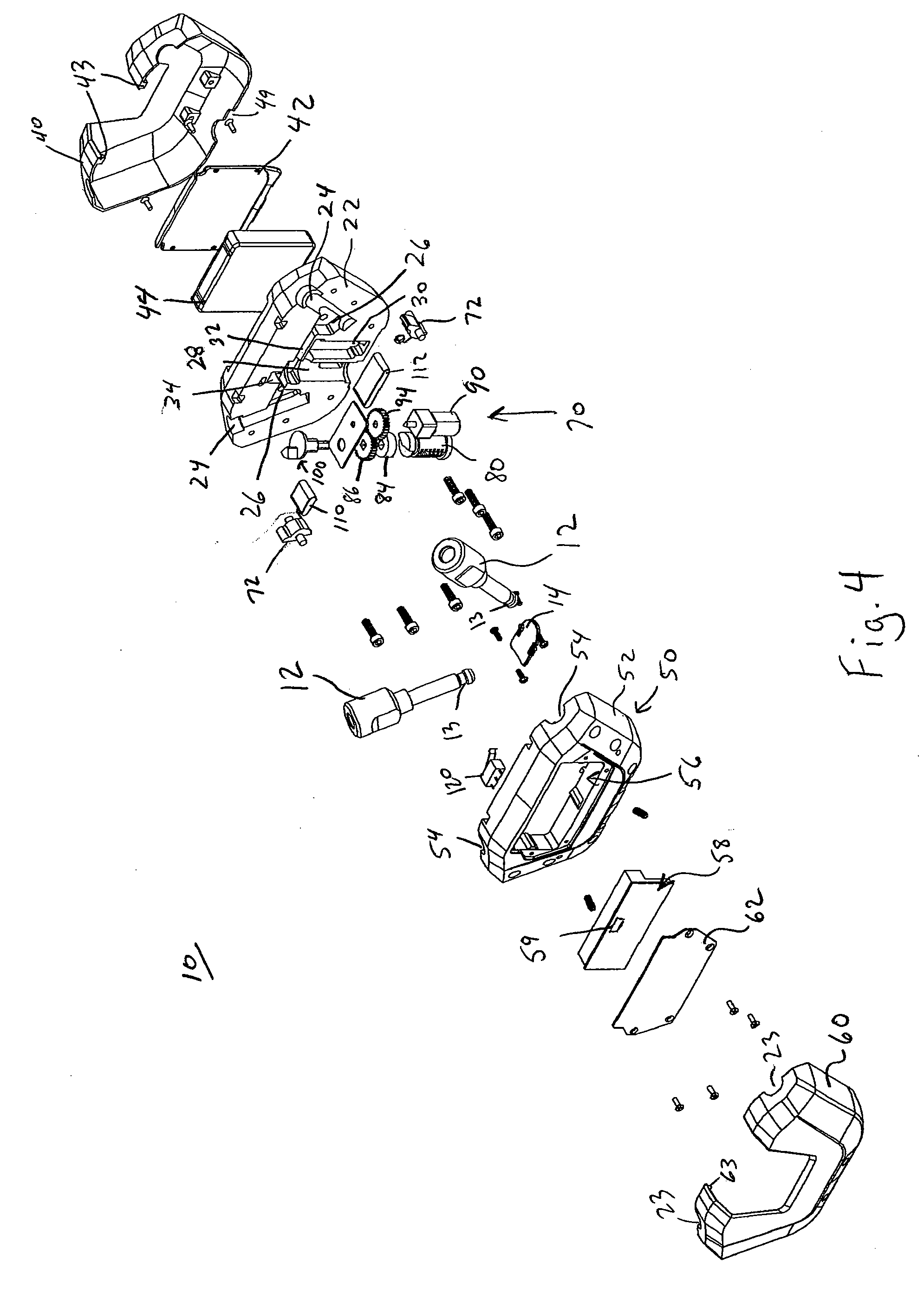
[0043]The illustrated embodiments described herein show cable locks and padlocks, however, the invention is not limited to such. The locks of the present invention may have various body configurations and locking member configurations. For example, the lock may be a cable lock, a padlock, a U-lock, a steering wheel lock or any other lock configuration.

[0044]Referring to FIGS. 1-10, a lock assembly 10 that is a first embodiment of the present invention will be described. The lock assembly 10 is in the form of a cable lock, but the invention is not limited to such. The lock assembly 10 includes a lock body 20 which defines a pair of locking member openings 23. In the present embodiment, each opening 23 is configured to receive a locking leg 12 (see FIGS. 7-10) of a cable lock, but the legs 12 may be of other lock designs. The lock body 20 includes a through opening 49 in which is aligned the key slot 83 of a key lock cylinder 80 configured to receive a key (not shown) to unlock the lo...


PUM


Abstract

A lock assembly including a body and at least one locking member. An actuator mechanism within the body is moveable between locked and unlocked positions. The actuator mechanism may be actuated by either a key lock cylinder or an electronic actuator. The lock assembly may also include a memory configured to store user identification information.

Description

BACKGROUND OF THE INVENTION[0001]The present invention relates to a portable lock. More particularly, the present invention relates to a portable lock with a housing and a locking member, the locking member releasable from a locked position via at least an electronic actuator.[0002]It is commonly known that when an individual is concerned about maintaining articles in a secure environment, people routinely use a variety of locking devices to secure receptacles wherein the material to be safeguarded is retained, such as, for example, safety deposit boxes and lockers. In such settings individuals utilize padlocks of either the key or combination variety on the latches of these containers so as to maintain the contents in a secure fashion. Standard padlocks widely available today consist of three basic types: 1) A standard key lock which operates on the basis of a tumbler system and is actuated by inserting a key into a cylinder at the base of the lock which contains pins or mechanical...

Claims


Application Information

Patent Timeline
Patent Type & Authority Applications(United States)
IPC IPC(8): E05B49/02E05B67/08G05B19/00
CPCE05B37/0031E05B47/0012E05B67/003E05B2047/0024E05B2047/0016E05B2047/002E05B67/24Y10S292/37Y10T70/5761Y10T70/483Y10T70/459Y10T70/7107Y10T70/713Y10T70/446Y10T70/7068Y10T70/415Y10T70/7073
Inventor ZURASKI, ROBERT D.MCDAID, CORNELIUSPAUL THAMBUSAMI JOY SACHIDANADAM, JOHN
Owner SCHLAGE LOCK
Why Eureka
Try Eureka