Dual on-center column lock mechanism

Inactive Publication Date: 2009-11-19
STEERING SOLUTIONS IP HLDG +1
View PDF8 Cites 15 Cited by
  • Summary
  • Abstract
  • Description
  • Claims
  • Application Information

AI Technical Summary

Benefits of technology

[0008]Accordingly, the subject invention provides a compact adjustable steering column assembly in which a mechanical interlocking interface, e.g., between the pawl and the telescope lock teeth, is disposed

Problems solved by technology

However, this configuration of the bolt and the various locking devices arranged above or below the column jacket require a significant amount of space.
However, the locking mechanism is not capabl

Method used


Image

  • Dual on-center column lock mechanism
  • Dual on-center column lock mechanism
  • Dual on-center column lock mechanism

Examples


Example

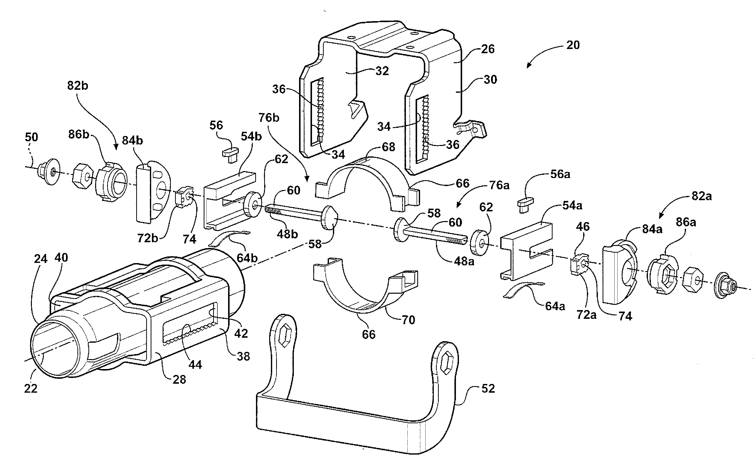
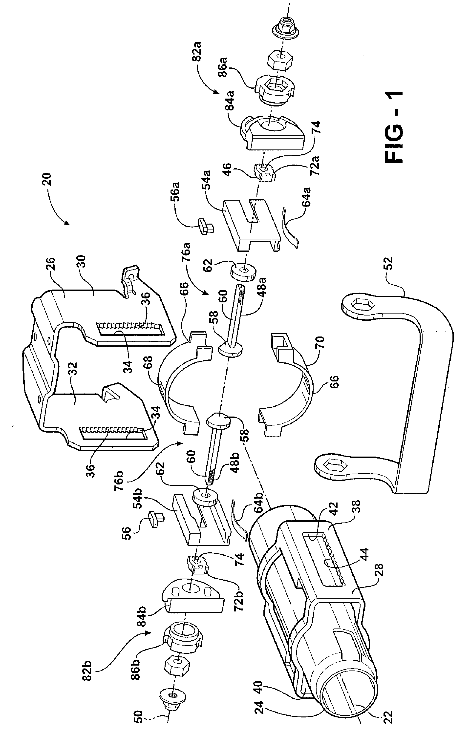
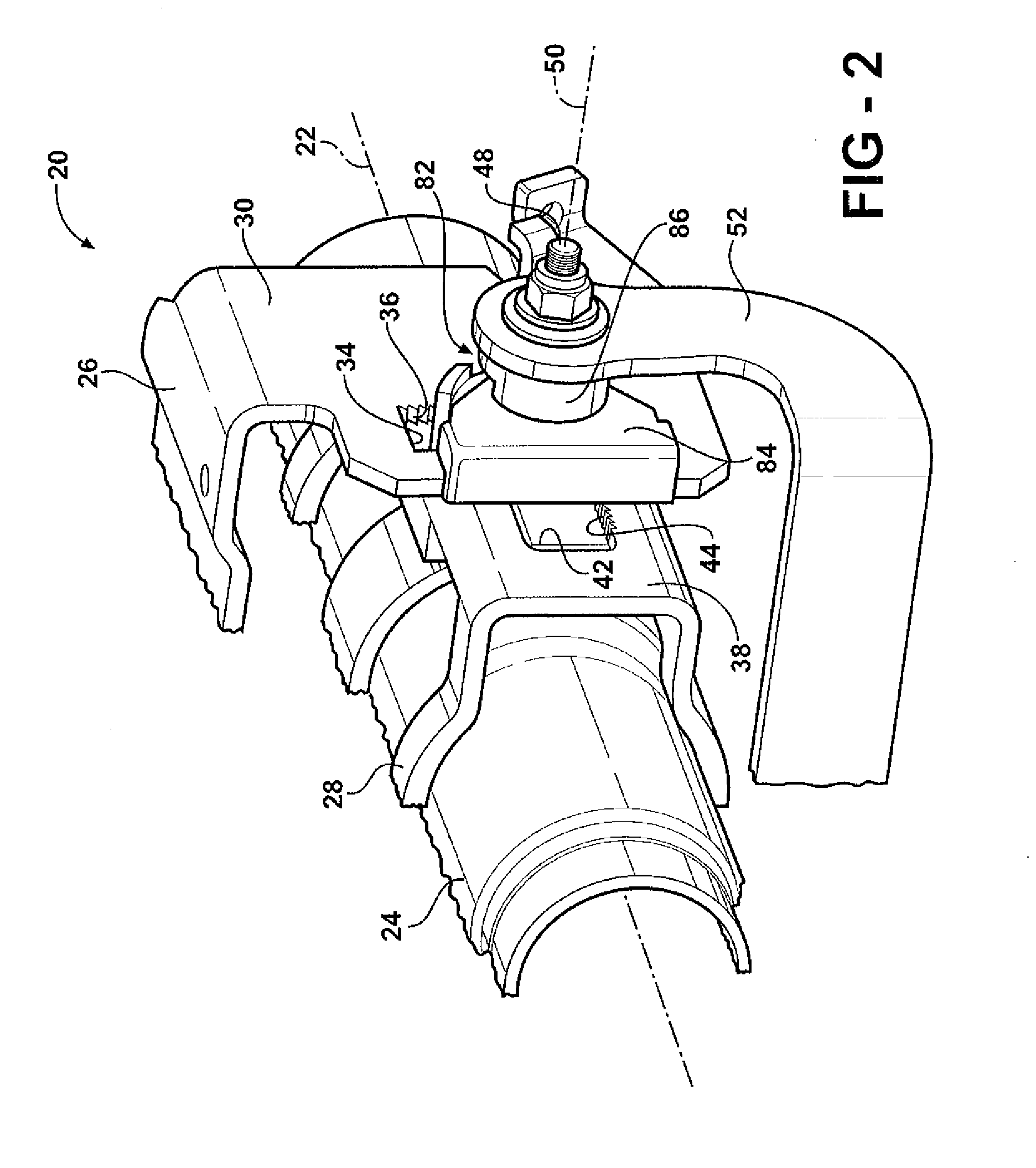
[0019]Referring to the Figures, wherein like numerals indicate corresponding parts throughout the several views, a steering column assembly is shown generally at 20. The steering column assembly 20 is for a vehicle, and is telescopically adjustable in a longitudinal direction along a longitudinal axis 22 and pivotably adjustable in a tilt direction transverse to the longitudinal axis 22. The steering column assembly 20 rotatably supports a steering wheel (not shown) as is well known.

[0020]Referring to FIGS. 1 and 2, the steering column assembly 20 comprises a column jacket 24. The column jacket 24 extends along the longitudinal axis 22. Preferably, the column jacket 24 includes a lower column jacket (not shown) and an upper column jacket. The upper column jacket is telescopically moveable along the longitudinal axis 22 relative to the lower column jacket to adjust a longitudinal position of the steering wheel. Preferably, the column jacket 24 includes a circular cross section. Howev...


PUM


Abstract

An adjustable steering column assembly includes a column jacket extending along a longitudinal axis. The column jacket includes a compression bracket mounted thereto, and is supported by a mounting bracket. A pawl engages a telescope slot defined by the compression bracket in interlocking engagement to mechanically lock the longitudinal position of the column jacket relative to the mounting bracket. A transverse cam mechanism moves the pawl generally vertically into and out of engagement with the telescope slot. An axial cam mechanism compresses the compression bracket against the mounting bracket. The transverse cam mechanism and the axial cam mechanism are operated by shaft extending along a shaft axis intersecting the column jacket. The transverse cam mechanism and the axial cam mechanism each include first and second cam mechanism disposed on opposing sides of the column jacket and simultaneously operable by a lever.

Description

BACKGROUND OF THE INVENTION[0001]1. Field of the Invention[0002]The subject invention generally relates to a steering column assembly for a vehicle. More specifically, the subject invention relates to an adjustable steering column assembly adjustable in at least one of longitudinal direction along a longitudinal axis and a pivotable direction transverse to the longitudinal axis.[0003]2. Description of the Prior Art[0004]Adjustable steering column assemblies include a locking mechanism to secure the position of a column jacket relative to a mounting bracket. The locking mechanism often employs a friction / compression locking device that applies a compressive force to compress the mounting bracket against the column jacket to hold the column jacket in place. The locking mechanism may additionally employ a positive locking device, such as interlocking teeth between members. The positive locking device holds the position of the column jacket relative to the mounting bracket in place duri...

Claims


Application Information

Patent Timeline
IPC IPC(8): B62D1/18
CPCB62D1/184
Inventor STRENG, JOSEPH R.GILBERT, AARON T.
Owner STEERING SOLUTIONS IP HLDG
Why Eureka
Try Eureka