External fixator

a fixator and external technology, applied in the field of external fixators, can solve the problems of low degree of freedom, limited direction of rod-like member, difficulty in accurately inserting the pin into the living body and adjusting the bones, etc., and achieves high degree of freedom, high strength, and high degree of freedom

Inactive Publication Date: 2009-11-19
NAGOYA UNIVERSITY
View PDF17 Cites 56 Cited by
  • Summary
  • Abstract
  • Description
  • Claims
  • Application Information

AI Technical Summary

Benefits of technology

[0050]When a plurality of ball joints are connected to one pin, the directions of the coupling members are not limited to one direction, so that it is possible to obtain an external fixator that has a very high degree of freedom in fixing. Further, if the external fixator is fixed while the coupling members are oriented in several directions, the external fixator can be fixed so as to have high strength against forces applied from various directions.
[0051]Furthermore, ball joints are connected to a plurality of pins so that one or more ball joints are connected to each of n (n is 2 or more) pins and n or more ball joints are connected in total. It is possible to give a very high degree of freedom to a relative positional relationship between the pin and the coupling member by fixing the pin and the coupling member by the ball joint. Accordingly, even though the plurality of pins are inserted into the bone in any direction, it is possible to connect the ball joints to each other by the coupling member without being affected by the directions and to fix the pins.
[0052]In addition, the limitation on a distance or angle between the pins (for example, the limitation where a plurality of pins should be inserted into a certain portion so as to parallel to each other) is removed by connecting different ball joints to a plurality of pins respectively, and the pins do not need to be disposed on the same plane. Accordingly, if the different ball joints are connected to each of the plurality of pins, it is possible to insert pins at the position and in the direction, which are required for resetting the bones, without the need to consider of the insertion angle of the pin when the external fixator is fixed. As a result, it is possible to provide a user-friendly external fixator.

Problems solved by technology

Since the insertion direction of the pin was limited in the above-mentioned external fixator, it was difficult to accurately insert the pin into the living body and to appropriately reset bones.
Further, the direction of a rod-like member, which connected one pin with the other pin, was limited.
Accordingly, when the external fixator was fixed, a degree of freedom was low and fixing strength was also low.
However, since the pins inserted into bones are fixed by clamps, a degree of freedom is also significantly limited when the pin is inserted.
When the pin is inserted into the living body, it is very difficult to accurately control the insertion position of the pin and it is not possible to insert the pin into the bone again.
Therefore, unless a very high degree of freedom is given to the insertion direction of the pin, it is very difficult to handle the external fixator.
Since the insertion direction of a pin is regulated by a clamp in these techniques, a degree of freedom in the insertion direction of the pin is low and it is very difficult to handle an external fixator.

Method used


Image

  • External fixator
  • External fixator
  • External fixator

Examples


Embodiment Construction

[0085]Herein, an embodiment of the present invention will be described in the following order.

(1) Schematic structure of external fixator:

(2) Structure of pin and rotary member:

(3) Structure of socket:

(4) Structure of coupling member:

(5) Other embodiments:

(1) Schematic Structure of External Fixator

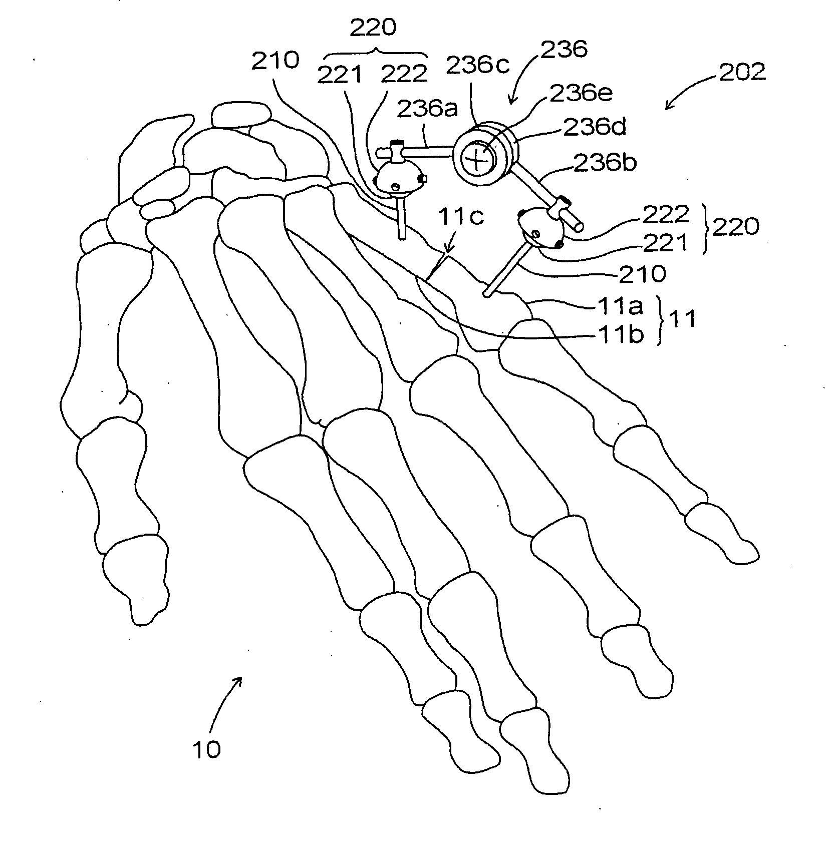
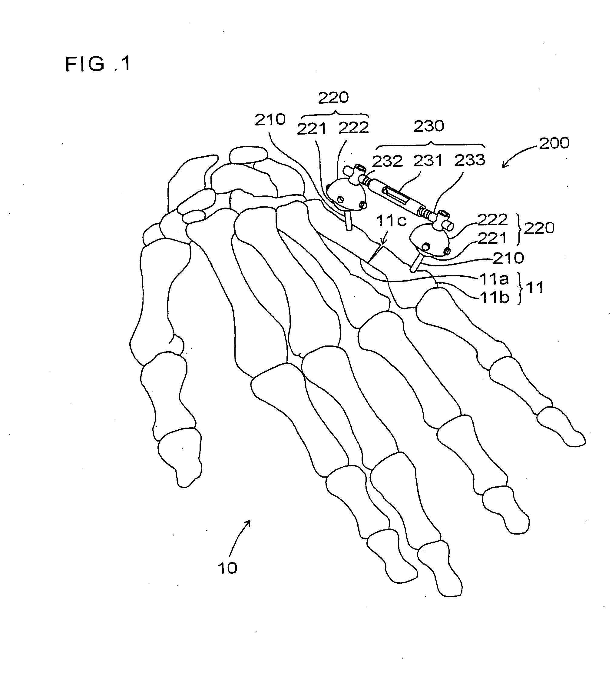
[0086]FIG. 1 is a view showing an external fixator according to an embodiment of the present invention. FIG. 1 shows bones 10 of a human hand and shows that one bone 11 of the bones is broken at a portion 11c. The broken bone 11 includes a bone 11a and a bone 11b, and an external fixator 200 according to this embodiment is fixed to the bones in order to fix the bones while the bones are reset.

[0087]In FIG. 1, pins 210 are inserted into the bones in order to reset the bone 11a and the bone 11b, respectively. When a treatment is performed, the pins 210 are pierced to the skin and the pins 210 are inserted into the bones 11a and 11b. A ball joint 220 is connected to an end of each of the pins...


PUM


Abstract

A work for fixing a bone by an external fixator is facilitated. The external fixator comprises a plurality of ball joints each comprising a plurality of pins inserted into a bone, a coupling member, a rotary member that fixes pins to the coupling member relatively, is coupled by the coupling member and forms a ball at least partially, a supporting member in which a first supporting member and a first screw for supporting the ball rotatably are formed, and a tubular fastening member that contains the ball, has openings at the opposite ends, is provided at one end with a second screw corresponding to the first screw, and is provided at the other end with a second supporting portion for pushing the ball against the first supporting portion when the second screw is driven into the first screw, wherein the pins and the coupling member are fixed to the supporting member and the rotary member.

Description

TECHNICAL FIELD[0001]The present invention relates to an external fixator that fixes broken bones.BACKGROUND ART[0002]An external fixator has been known as a device that resets and fixes bones during the treatment of broken bones.[0003]In general, an external fixator includes pins that are inserted into bones and members that connect the pins. The members and the pins are fixed not to move relative to each other, so that the bones are reset and fixed.[0004]For example, in Japanese Patent No. 3740640, a plurality of pins are inserted into portions where bones are broken, and the plurality of pins are fixed at each of the portions by clamps. Further, the clamps are connected and fixed to each other by rod-like members that include ball joints at both ends thereof. Japanese Unexamined Patent Application Publication No. 10-43204 also discloses a technique where a plurality of pins are fixed by clamps and ball joints are connected to the clamps.[0005]Furthermore, PCT Japanese Translation...

Claims


Application Information

Patent Timeline
Patent Type & Authority Applications(United States)
IPC IPC(8): A61F5/04
CPCA61B17/6416A61B17/66A61B17/6466A61B17/645A61B17/58A61B17/60A61B17/86
Inventor HIRATA, HITOSHITATEBE, MASAHIROSHINOHARA, TAKAAKI
Owner NAGOYA UNIVERSITY
Why Eureka
Try Eureka