Dry sprinkler system and design methods

a technology of dry sprinklers and sprinklers, applied in the field of dry sprinkler fire protection systems, can solve the problems of dry sprinkler systems, unlike wet systems, present delay, dry sprinkler systems are inferior to wet systems, otherwise impractical,

Inactive Publication Date: 2009-11-26
TYCO FIRE PRODS LP
View PDF14 Cites 25 Cited by
  • Summary
  • Abstract
  • Description
  • Claims
  • Application Information

AI Technical Summary

Benefits of technology

The preferred dry sprinkler system has a primary water control valve that separates the wet and dry parts of the system. The dry part includes at least one hydraulically remote sprinkler and at least one hydraulically close sprinkler relative to the control valve. The system also has a minimum and maximum fluid delivery delay period, which determines the time it takes to deliver fluid from the control valve to the closest sprinkler. The technical effect of this system is that it allows for controlled separation between the wet and dry parts of the system, and ensures efficient and effective fire protection.

Problems solved by technology

The technical problem addressed in this patent text is the delay in the operation of dry sprinkler systems due to the fluid delivery delay caused by the design of the system. The delay can impact the performance of the system and make it difficult to design and install the system. The patent text discusses the factors that affect the delay, such as the volume of the system, the hydraulic characteristics of the system, and the design of the system. The text proposes a method to predict the time it takes for a dry system to activate the sprinkers and release the water from the system. The method aims to minimize the delay and improve the performance of dry sprinkler systems.

Method used


Image

  • Dry sprinkler system and design methods
  • Dry sprinkler system and design methods
  • Dry sprinkler system and design methods

Examples


Embodiment Construction

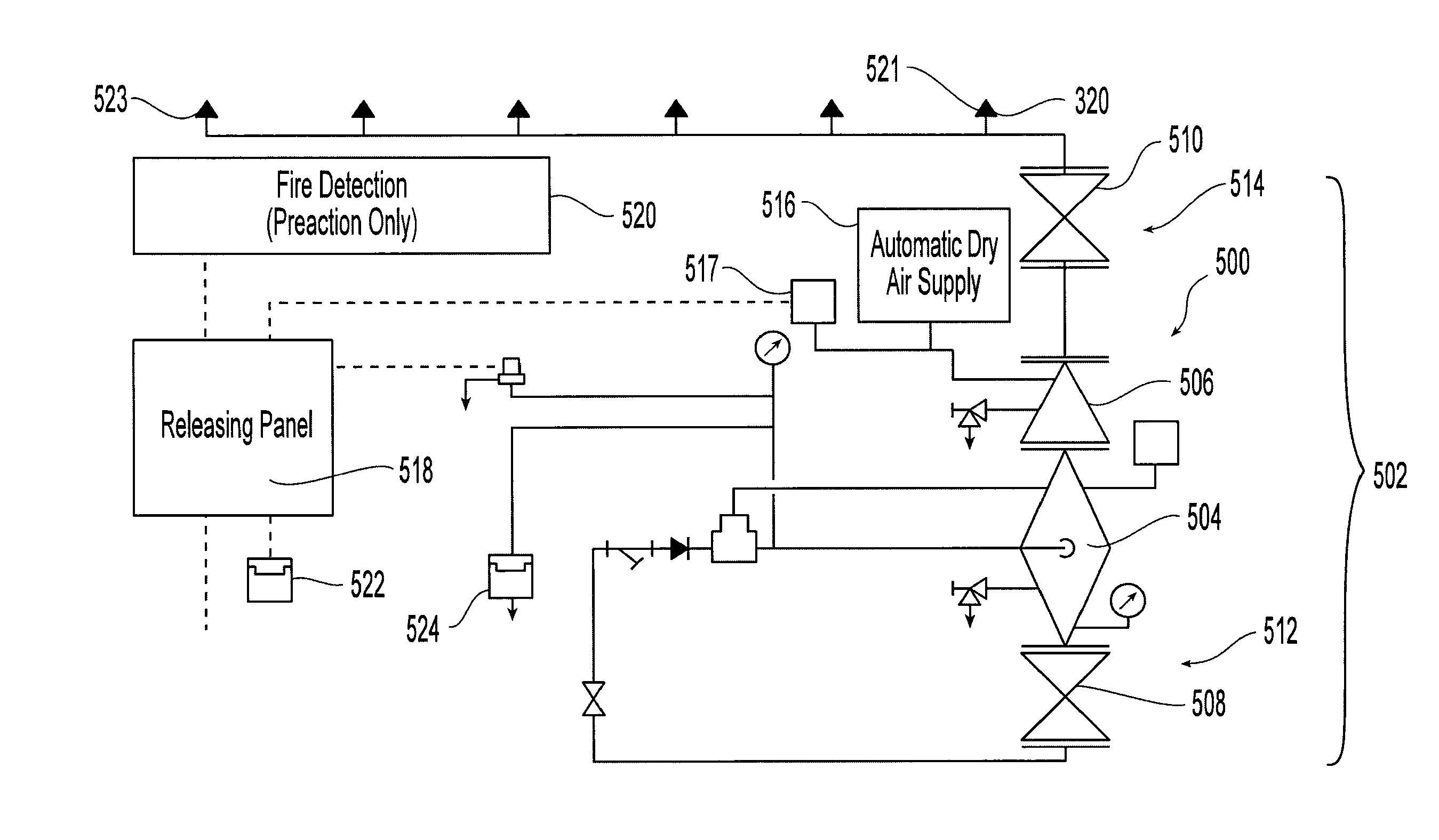
[0035]A preferred methodology for the design of a dry sprinkler system can be provided in which the dry sprinkler system has an operational performance equivalent to that of a wet system. More specifically, the preferred methodology provides for designing a dry sprinkler fire protection system to protect a storage occupancy having a defined ceiling height to store a commodity of a defined commodity class, storage configuration and storage height. The dry sprinkler system is preferably configured to hydraulically perform the same as a wet system configured to protect a substantially similar storage occupancy and commodity arrangement. Accordingly, the preferred method of dry sprinkler design is based upon the use of wet sprinkler performance as a bench mark.

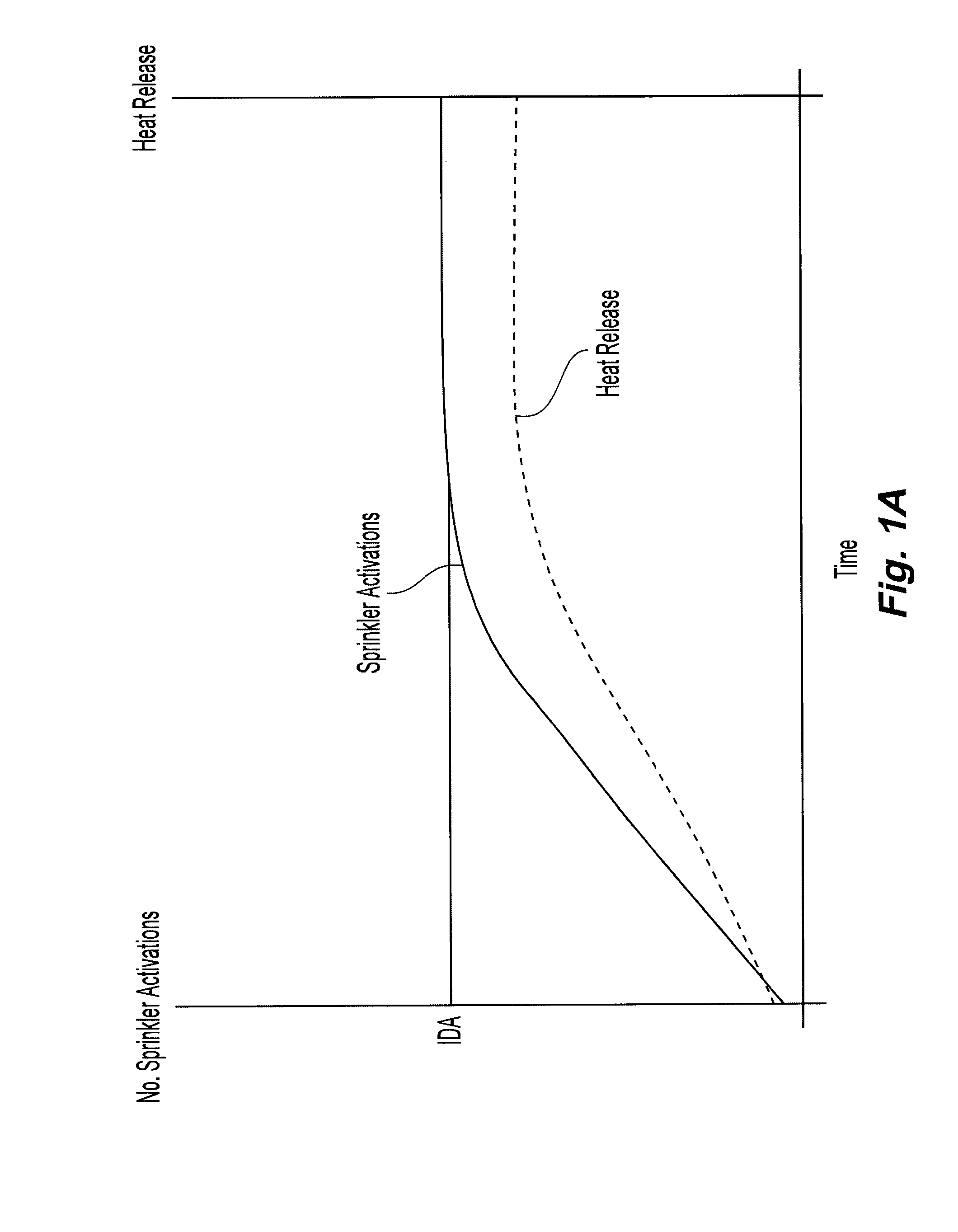
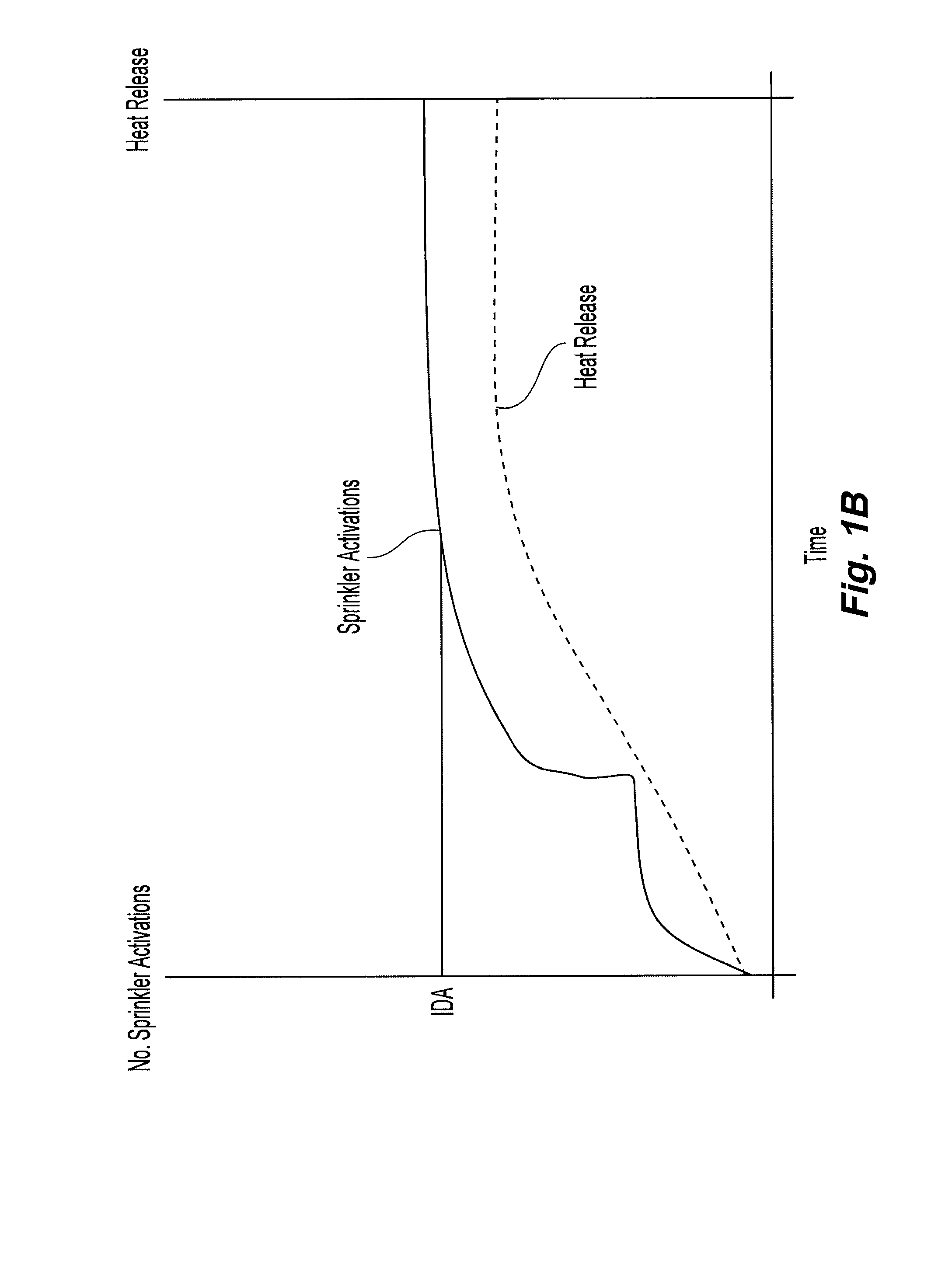
[0036]In particular, the preferred design methodology relies upon a presumption about wet sprinkler performance. It is believed that a wet sprinkler system has an inherent design area (IDA) which is defined by a total number of th...


PUM


Abstract

A dry fire protection system, preferably for a storage occupancy, and its method of design are provided in which a fluid delivery delay period is identified and implemented. The preferred design method includes defining a ceiling height, a storage configuration, and storage height. The hydraulic demand for a wet system protecting the same defined storage occupancy is then identified. A fluid delivery delay period is then determined for the dry sprinkler system, preferably a maximum ADT, which results in a sprinkler operational area having a total number of sprinkler activations less than or equal to that defining the total hydraulic demand of the wet system. The preferred dry system can be further configured such that each and every sprinkler in the system has a fluid delivery delay period equal to or less than the maximum fluid delivery delay period.

Description


Claims


Application Information

Patent Timeline
Owner TYCO FIRE PRODS LP
Why Eureka
Try Eureka