Dynamic latch circuitry

a latch circuit and dynamic technology, applied in logic circuits, pulse generators, pulse techniques, etc., can solve the problems of incorrect latching of data, data outputs that cannot be evaluated, and the safety margin of latching data is reduced, so as to improve efficiency, reduce size, and enhance operating characteristics

Inactive Publication Date: 2000-07-11
GLOBALFOUNDRIES INC
View PDF5 Cites 22 Cited by
  • Summary
  • Abstract
  • Description
  • Claims
  • Application Information

AI Technical Summary

Benefits of technology

The present invention is a high-performance dynamic flip-flop characterized by improved efficiency, enhanced operating characteristics, and reduced size. Flip-flops are a basic logic element used to build digital...

Problems solved by technology

However, a delay 448 which is too short creates problems too.
For example, among other problems, a very short delay 448 also decreases the safety m...

Method used


Image

  • Dynamic latch circuitry
  • Dynamic latch circuitry
  • Dynamic latch circuitry

Examples


Embodiment Construction

The present invention is a flip-flop circuit. A flip-flop is a basic logical building block used to create larger, more complex logic circuits. For example, flip-flops may be used in the design of many types of electronic and digital systems including computer systems, telecommunication systems, networking systems, manufacturing systems, graphical systems, consumer systems, and numerous other types of systems. Moreover, the present invention may be embodied on integrated circuits, which may be used to build these systems. In particular, the present invention may be used in microprocessors, memories, ASICs, gate arrays, field programmable gate arrays, programmable logic devices, and many others types of products.

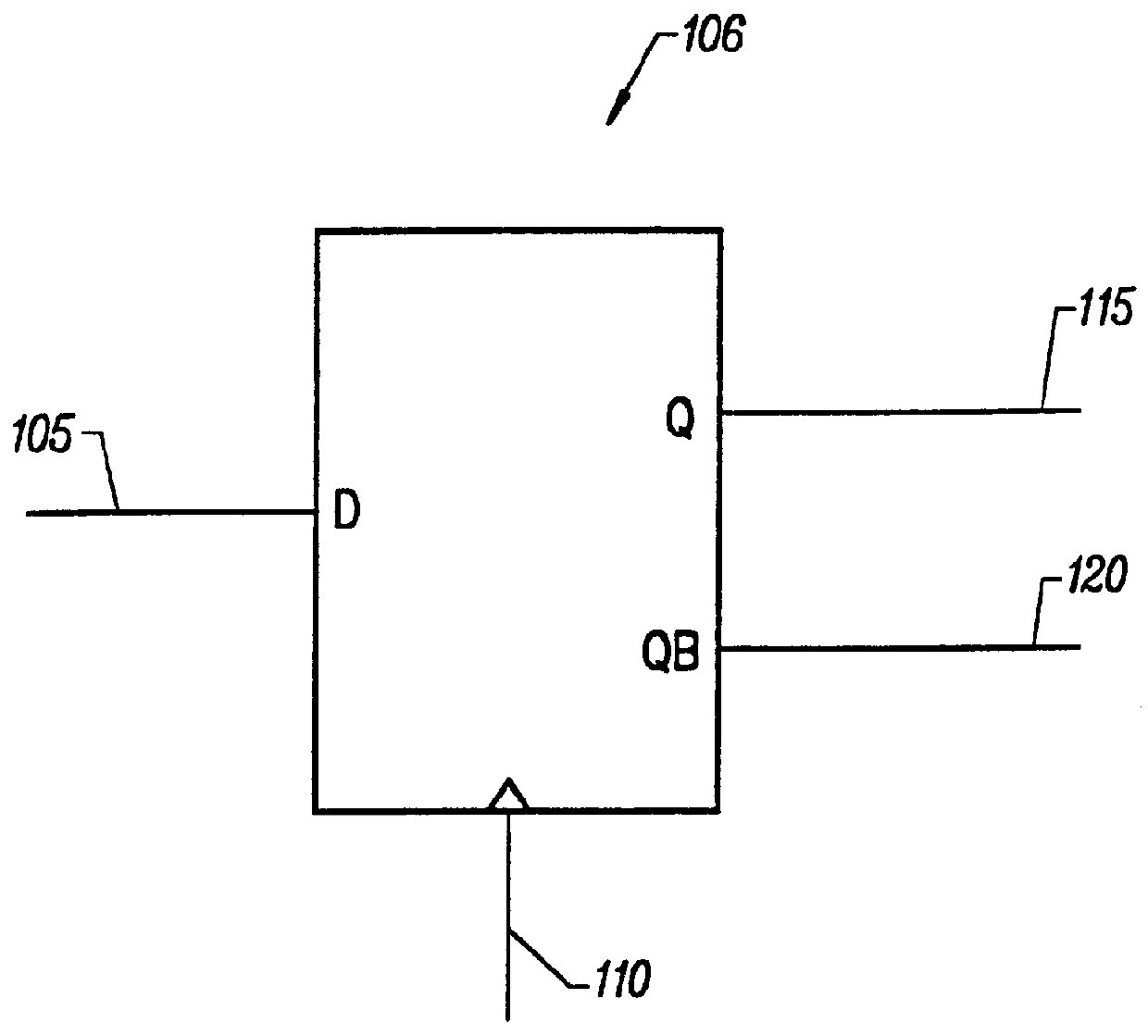
FIG. 1 is a diagram of a flip-flop 100. FIG. 1 shows the logic symbol for a basic D-type flip-flop. There are many other types of flip-flops such as T, S-R, and J-K flip-flops. In fact, D flip-flops may be used in the implementation of these other types of flip-flops. In this...


PUM


Abstract

A high-performance dynamic flip-flop circuit implementation. The dynamic flip-flop circuit comprises an "implicit" one-shot to generate a delayed clock output (319). The flip-flop comprises a delay block (317) coupled to a clock input (305). The flip-flop may be a D-type flip-flop. In a positive-edge-triggered embodiment of the flip-flop, a falling edge (440) of the delayed clock output (319) follows a rising edge (444) of a clock signal after a delay period (448). The flip-flop clocks in new data at a data input (305) in response to the clock input (310) during this delay period (448). Data is held in a storage block (360). The flip-flop has extremely good transient characteristics, especially set-up and clock-to-output times. The flip-flop consumes no static power.

Description

BACKGROUND OF THE INVENTIONThis invention relates to the field of digital logic circuits. More specifically, the present invention is a high-performance flip-flop circuit, especially useful in the design of high-performance electronic circuits.A digital system is made up of logic elements including AND gates, OR gates, NAND gates, NOR gates, inverters, flip-flops, multiplexers, and many others. These basic logic elements are combined and used to create larger, more complex logic functions such as registers, shifters, accumulators, state machines, processing units, and microprocessors, to name a few. These functions may be embodied on integrated circuits, printed circuit boards, and other similar techniques. Ultimately, these logic elements are used to create digital systems, which may contain millions of logic elements, or even more. Some examples of digital systems are computers, automated teller machines, modems, network servers, telecommunications systems, global positioning syst...

Claims


Application Information

Patent Timeline
IPC IPC(8): H03K3/12H03K3/00
CPCH03K3/12H03K19/0963
Inventor PARTOVI, HAMIDBURD, ROBERT C.SALIM, UDINWEBER, FREDERICKDI GREGORIO, LUIGIDRAPER, DONALD A.
Owner GLOBALFOUNDRIES INC
Why Eureka
Try Eureka