Apparatus and method for controlling switching power supply

a technology of switching power supply and apparatus, applied in the direction of dc-dc conversion, power conversion systems, instruments, etc., can solve the problems of error caused by loss on the secondary side, output voltage is changed from its target value, etc., to achieve the effect of minimizing errors

Active Publication Date: 2016-12-22
FUJI ELECTRIC CO LTD
View PDF7 Cites 21 Cited by
  • Summary
  • Abstract
  • Description
  • Claims
  • Application Information

AI Technical Summary

Benefits of technology

This invention is about a device that controls a switching power supply. It uses a transformer to convert input voltage into a direct current output voltage. The device includes a unit that measures the output voltage and compares it to a target level. The result of the measurement is added to a reference voltage to create a feedback signal. This feedback signal is used to control the pulse width modulation (PWM) of the switching element in order to maintain a constant output voltage. The invention provides a precise and efficient way to control the output voltage of a switching power supply.

Problems solved by technology

However, in reality, since a voltage drop is caused by a diode and the like arranged on the secondary side, the output voltage is changed from its target value, and an error is caused.
Thus, according to the above conventional techniques, the error caused by the loss on the secondary side cannot completely be eliminated.

Method used


Image

  • Apparatus and method for controlling switching power supply
  • Apparatus and method for controlling switching power supply
  • Apparatus and method for controlling switching power supply

Examples


Embodiment Construction

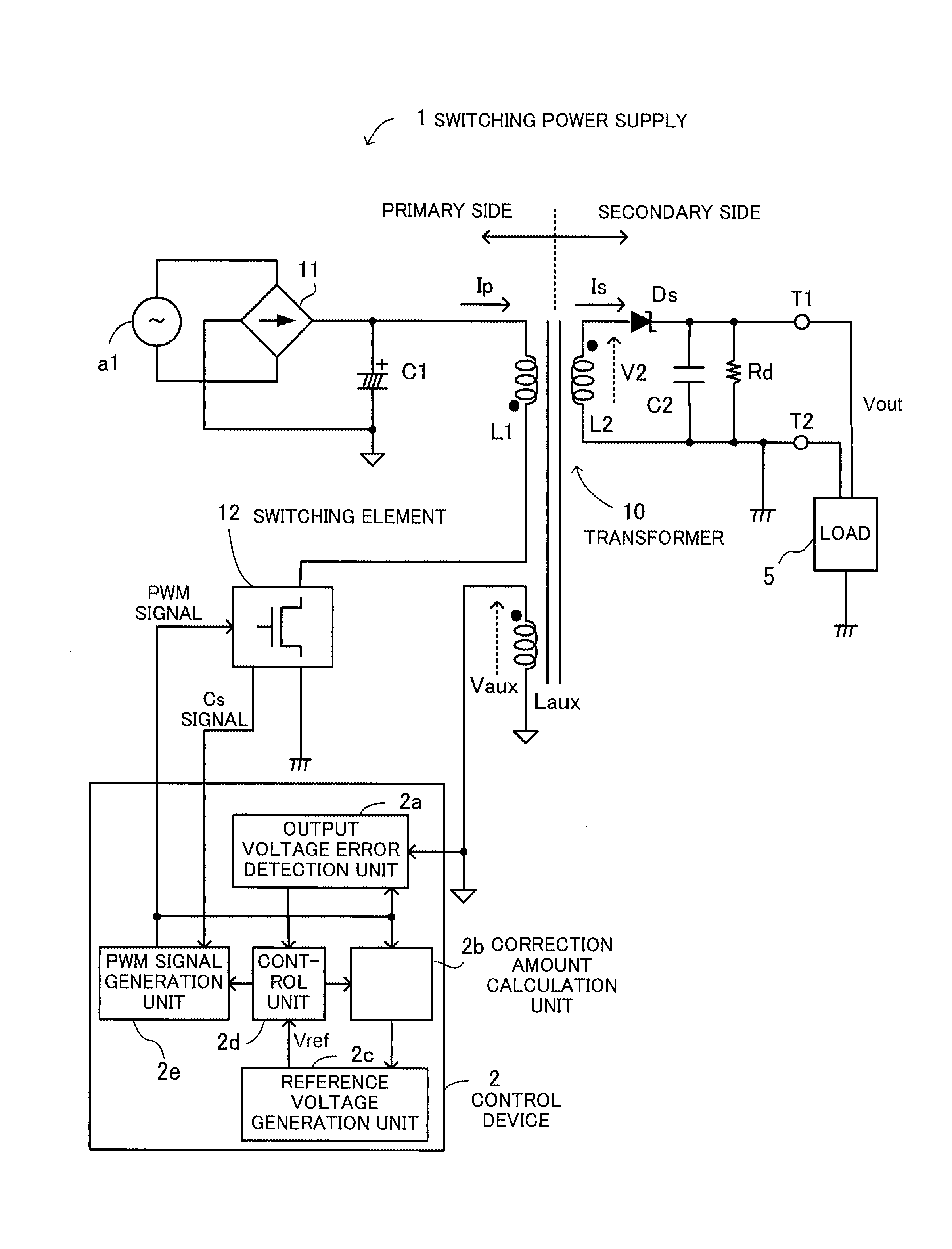
[0032]Embodiments will be described below with reference to the accompanying drawings, wherein like reference characters refer to like elements throughout. FIG. 1 illustrates an example of a configuration of a switching power supply 1. The switching power supply 1 includes a transformer 10, a bridge circuit 11, a switching element 12, an input capacitor C1, a diode Ds, an output capacitor C2, a resistor Rd, and a control device 2.

[0033]The bridge circuit 11 rectifies an AC voltage outputted from an AC voltage source al. The input capacitor C1 smoothes and converts the rectified voltage into a DC voltage.

[0034]The transformer 10 includes a primary winding L1, a secondary winding L2, and an auxiliary winding Laux and transmits the energy generated on the primary side to the secondary side. The diode Ds rectifies the voltage generated by the secondary winding L2.

[0035]The output capacitor C2 smoothes the rectified voltage. The smoothed voltage is applied to a load 5 connected to output...


PUM


Abstract

An output voltage error detection unit outputs an auxiliary winding voltage generated across an auxiliary winding having the same number of turns as a secondary winding a certain period after a secondary conduction period starts. A correction amount calculation unit calculates a secondary voltage drop caused by a secondary current flowing in the conduction period based on a primary current flowing when the conduction period starts and outputs a calculation result as a correction amount. A reference voltage generation unit generates a reference voltage by adding the correction amount to the output voltage. A control unit generates a feedback signal to minimize the error between the auxiliary winding voltage obtained after a certain delay period and the reference voltage. A PWM signal generation unit controls a PWM signal based on the feedback signal, adjusts switching of the switching element, and maintains the output voltage at a constant level.

Description

CROSS-REFERENCE TO RELATED APPLICATION[0001]This application is based upon, and claims the benefit of priority of, the prior Japanese Patent Application No. 2015-122171, filed on Jun. 17, 2015, the entire contents of which are incorporated herein by reference.BACKGROUND OF THE INVENTION[0002]1. Field of the Invention[0003]The embodiments discussed herein relate to an apparatus and a method for controlling a switching power supply.[0004]2. Background of the Related Art[0005]Many switching power supplies use a flyback topology for the alternate current (AC) / direct current (DC) converter.[0006]Such a flyback switching power supply includes a transformer and a switching transistor such as a metal oxide semiconductor field effect transistor (MOSFET), causes a diode bridge to rectify an AC input voltage, and obtains a desired DC output voltage from the rectified voltage.[0007]In addition, such an AC / DC converter is provided with a control circuit to supply a stable output voltage even whe...

Claims


Application Information

Patent Timeline
IPC IPC(8): H02M3/335H02M1/32
CPCH02M1/32H02M3/33507H02M3/33523H02M1/0025
Inventor KAWASHIMA, TETSUYA
Owner FUJI ELECTRIC CO LTD
Why Eureka
Try Eureka