Multi-protocol low latency automatic speed negotiation architecture for an embedded high speed serial interface in a programmable logic device

a high-speed serial interface and automatic speed negotiation technology, applied in the field of high-speed serial interfaces, can solve problems such as reaching the maximum possible ra

Active Publication Date: 2010-03-23
ALTERA CORP
View PDF6 Cites 24 Cited by
  • Summary
  • Abstract
  • Description
  • Claims
  • Application Information

AI Technical Summary

Problems solved by technology

However, because each step is being approached from a lower rate, the lack of error at a particular step is not conclusive evidence that the maximum possible rate has been reached.

Method used


Image

  • Multi-protocol low latency automatic speed negotiation architecture for an embedded high speed serial interface in a programmable logic device
  • Multi-protocol low latency automatic speed negotiation architecture for an embedded high speed serial interface in a programmable logic device
  • Multi-protocol low latency automatic speed negotiation architecture for an embedded high speed serial interface in a programmable logic device

Examples


Embodiment Construction

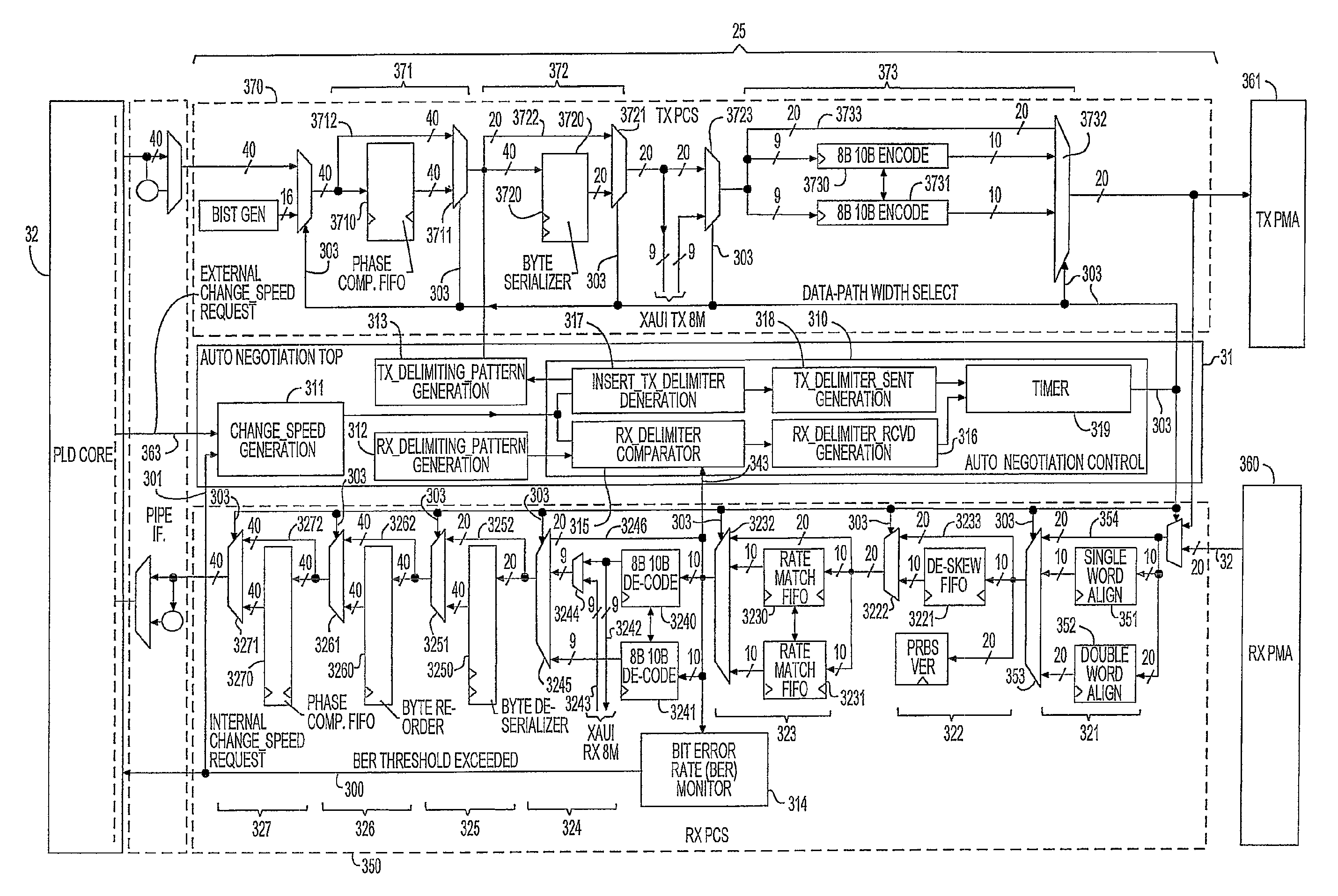
[0027]As described above, the present invention provides a high-speed serial interface that incorporates a hardware automatic speed negotiation module that allows negotiation of the data rate on a serial interface channel to occur within the short time windows provided by newer serial interface protocols.

[0028]The invention will now be described with reference to FIGS. 1-4.

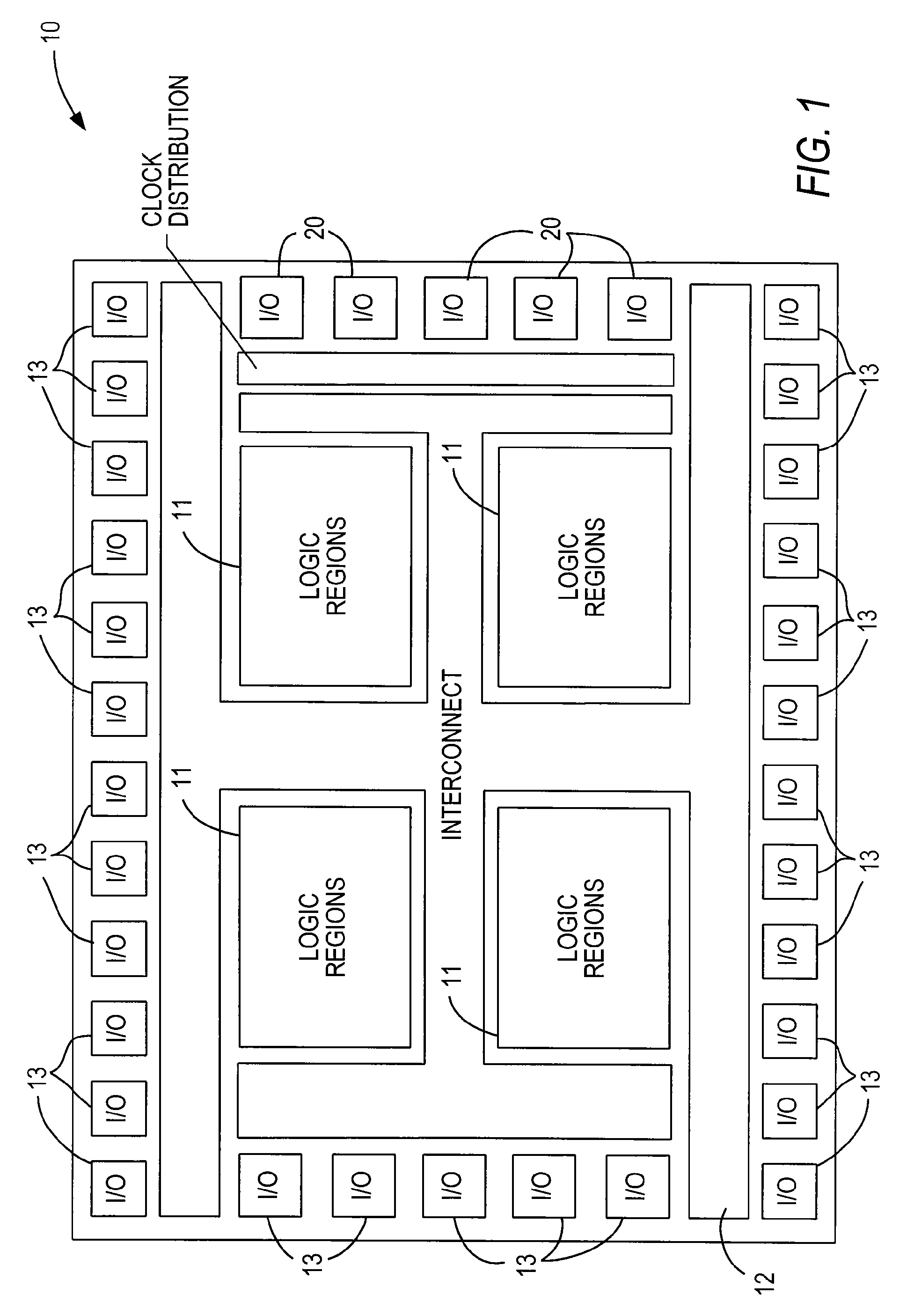
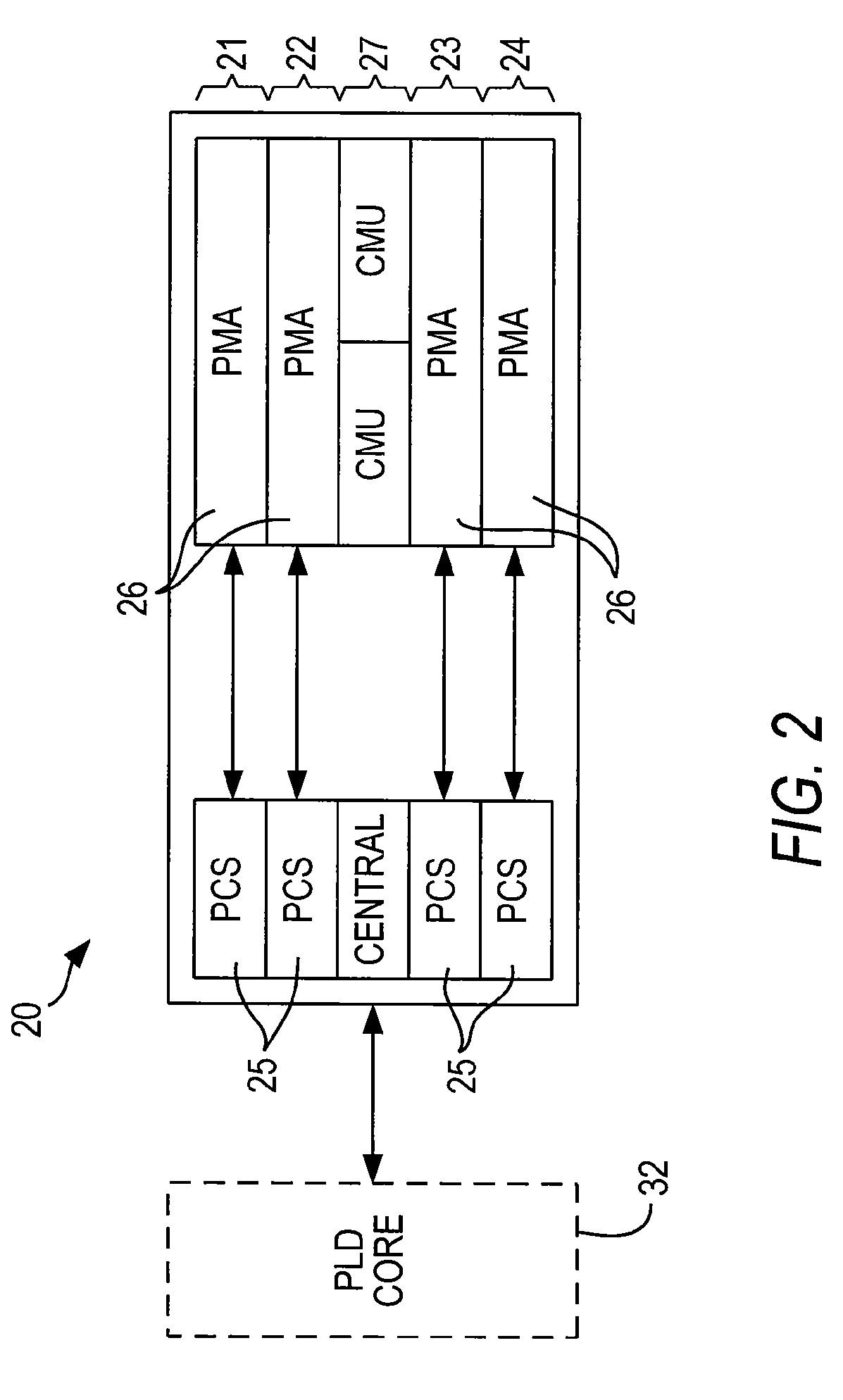
[0029]PLD 10, shown schematically in FIG. 1, is one example of a device including a serial interface 20 incorporating the invention. PLD 10 has a programmable logic core including programmable logic regions 11 accessible to programmable interconnect structure 12. The layout of regions 11 and interconnect structure 12 as shown in FIG. 1 is intended to be schematic only, as many actual arrangements are known to, or may be created by, those of ordinary skill in the art.

[0030]PLD 10 also includes a plurality of other input / output (“I / O”) regions 13. I / O regions 13 preferably are programmable, allowing the selection of...


PUM


Abstract

A serial interface for a programmable logic device includes receiver and transmitter portions, and an automatic speed negotiation module to adjust the data rates of both portions. The speed adjustment may be accomplished by adjusting the widths of the data paths in both portions. The speed adjustment occurs on receipt of a control signal generated elsewhere on the programmable logic device, or generated by the module. One reason for generating the control signal is the detection of data errors in the received data, or the detection of a delimiter pattern in the received data signifying that a remote device is about to change its data rate.Similarly, before changing its data rate, the module may insert a delimiter in the data in the transmitter portion. After receipt or transmission of a delimiter pattern, the module may wait for a predetermined delay period to elapse before changing the data rate.

Description

CROSS REFERENCE TO RELATED APPLICATION[0001]This claims the benefit of copending, commonly-assigned U.S. Provisional Patent Application No. 60 / 751,860, filed Dec. 20, 2005, which is hereby incorporated by reference herein in its entirety.BACKGROUND OF THE INVENTION[0002]This invention relates to a high-speed serial interface, especially in a programmable logic device (PLD), which may operate at different data rates.[0003]It has become common for PLDs to incorporate high-speed serial interfaces to accommodate high-speed (i.e., greater than 1 Gbps) serial I / O standards—e.g., the XAUI (Extended Attachment Unit Interface) standard. In accordance with the XAUI standard for example, a high-speed serial interface includes transceiver groups known as “quads,” each of which includes four transceivers and some central logic.[0004]In one implementation, each transceiver is divided into a physical medium attachment (PMA) portion or module which communicates with outside devices, and a physical ...

Claims


Application Information

Patent Timeline
Patent Type & Authority Patents(United States)
IPC IPC(8): H04B3/46
CPCH04L1/0002
Inventor VIJAYARAGHAVAN, DIVYALEE, CHONG H.
Owner ALTERA CORP
Why Eureka
Try Eureka