Tilt mounting system

a mounting system and tilting technology, applied in the field of tilting mounting systems, can solve the problems of difficult access and adjustment, limited display options of such devices, and large floor space in entertainment centers, and achieve the effect of promoting smooth movement of the carrier mechanism and reducing sliding

Active Publication Date: 2009-11-26
PEERLESS INDS
View PDF47 Cites 14 Cited by
  • Summary
  • Abstract
  • Description
  • Claims
  • Application Information

AI Technical Summary

Benefits of technology

[0009]The present invention comprises a self-balancing flat panel television or display mounting system. The mounting system is tiltable through the use of a plurality of substantially straight guide paths or surfaces formed with a mounting bracket and an adapter bracket, where carrier mechanisms are used to effectuate a smooth, rolling connection between the mounting bracket and the adapter bracket. In this arrangement, the resultant forces on the carrier mechanisms are oriented substantially perpendicular to the direction of the carrier mechanisms' travel, balancing the forces created by the supported load. By using a plurality of sets of guide paths with each support plate / mounting bracket combination, the guide paths create a “scissoring” action which diminishes sliding and promotes the smooth movement of the carrier mechanisms with the guide paths, as well as helping to ensure that the carrier mechanisms do not slip when a user or installer lifts and removes the television from the remainder of the mount.

Problems solved by technology

Because conventional “tube” televisions have a relatively large depth, the display options for such devices are quite limited.
Such stands or entertainment centers can take up significant floor space, which is often undesirable.
However, these systems usually require professional installation and, once the television is secured in the mount, it is often very difficult to access and adjust due to its height.
Although the introduction of flat-panel televisions on a wide scale has presented new opportunities to both residential and commercial customers, it has also presented new challenges.
Over the past few years, a number of wall mounting systems have been developed for use with flat panel televisions, but each has their own drawbacks.
Unfortunately, the curved slots themselves can cause the mounting systems' rolling pins to slip during the tilting process, which can lead to the mounting bracket, and therefore the attached television or display, to move in an abrupt, non-smooth fashion relative to the support bracket.
Such movements can make it difficult for one to precisely position the television or display in the desired position.
Additionally, gravity can, on occasion, cause the rolling pins to fall within the slots, which can cause the system to bind.
In such a situation, it becomes more difficult to adjust the orientation of the flat panel display.
Furthermore, with some newer plasma and LCD televisions being more sensitive and delicate than conventional tube televisions, such sudden slippage could also damage the devices.
However, such glides may be more expensive to manufacture than rolling pins, are more difficult to assemble into the curved slots than the rolling pins, and are prone to suffering wear to the frictional sliding of the glides against the sides of the slots.

Method used


Image

  • Tilt mounting system
  • Tilt mounting system
  • Tilt mounting system

Examples


Embodiment Construction

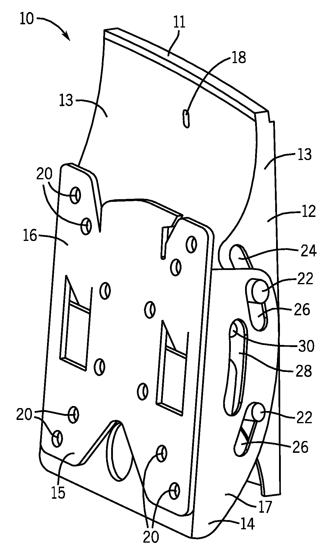
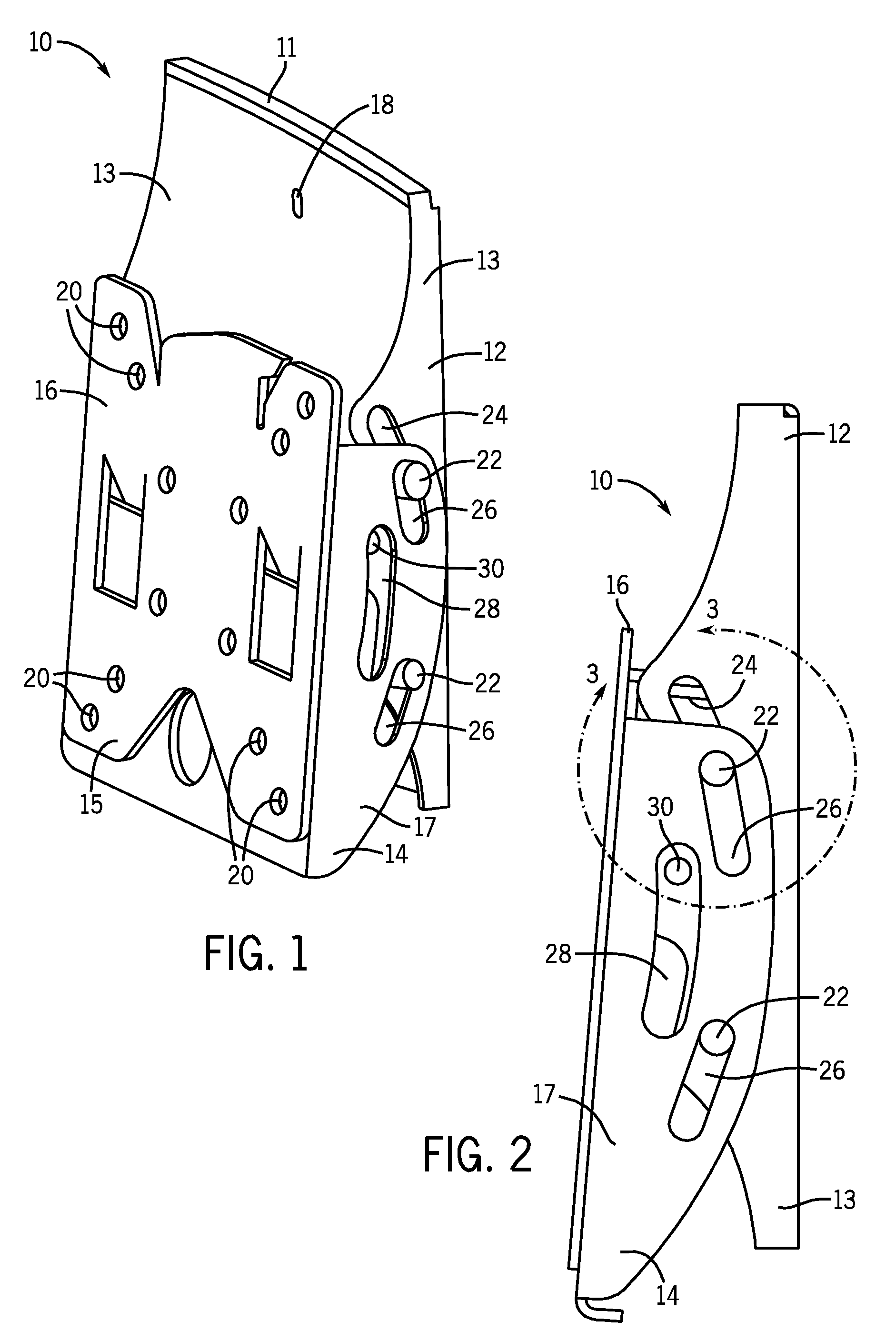
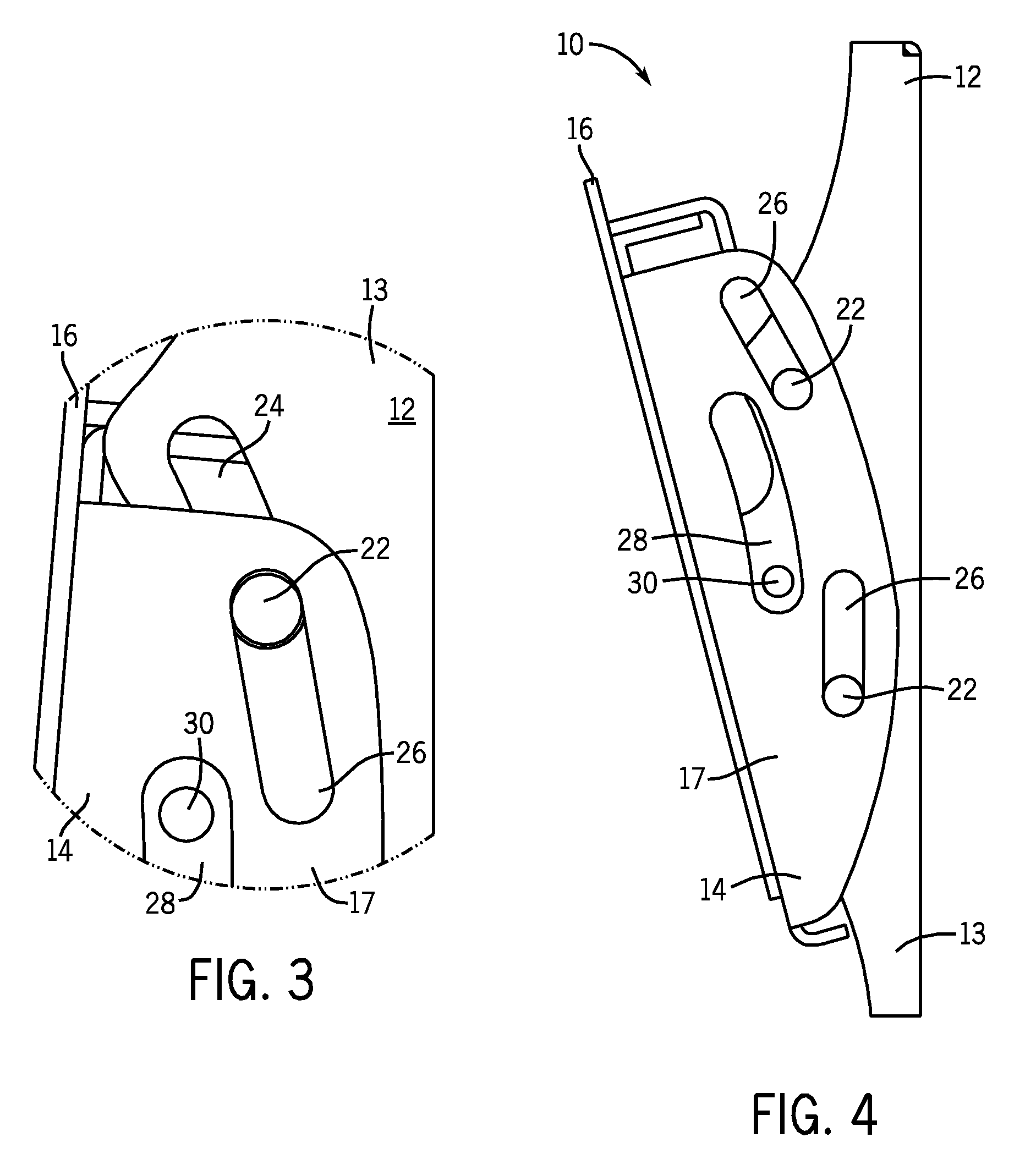
[0018]FIGS. 1-6 show an adjustable mounting system 10 constructed in accordance with one embodiment of the present invention. The mounting system 10 of FIGS. 1-6 comprises a mounting bracket 12 which is configured to attach to a flat surface such as a wall. The mounting bracket includes a mounting bracket contact portion 11 and a pair of mounting bracket flanges 13 on each side thereof. In the embodiment shown in FIGS. 1-6, a plurality of mounting bracket holes 18 are strategically placed and sized within the mounting bracket contact portion 11 to attach the mounting bracket 12 to the wall. It should also be noted, however, that the mounting bracket 12 can be part of a larger support system, and that the attachment of the mounting bracket 12 to the wall does not have to be direct. Instead, the mounting bracket 12 can be connected to the wall via a plurality of intermediate components, such as an articulating arm (not shown) or other brackets or plates. These various components can b...


PUM


Abstract

An improved adjustable mounting system for mounting a flat panel display to a surface. A mounting bracket is configured to attach to the surface, while an adapter bracket is operatively connected to the mounting bracket and is configured to operatively connect to the flat panel display. At least one carrier mechanism operatively connects the mounting bracket and the adapter bracket, the first carrier mechanism positioned with a set of substantially straight guide paths or surfaces to couple the adapter bracket to the mounting bracket. When the flat panel display is operatively connected to the adapter bracket and the mounting bracket is attached to the surface, the flat panel display is generally selectively rotatably positionable about an axis substantially parallel to the surface as a result of the interaction of the first carrier mechanism with the set of substantially straight guide paths or surfaces.

Description

CROSS REFERENCE TO RELATED PATENT APPLICATIONS[0001]The present application is a continuation of U.S. patent application Ser. No. 11 / 357,348, filed Feb. 17, 2006, which claims priority to U.S. Provisional Patent Application No. 60 / 728,945, filed Oct. 21, 2005. The contents of these applications are incorporated herein by reference in their entirety.FIELD OF THE INVENTION[0002]The present invention relates generally to mounting systems. More particularly, the present invention relates to adjustable mounting systems for mounting devices such as flat panel televisions and displays on a surface.BACKGROUND OF THE INVENTION[0003]In recent years, flat-panel television units have become enormously popular in both the commercial and the residential sectors. As the prices for plasma and liquid crystal display (LCD) flat panel displays have continued to fall, and as the quality for the same devices have improved, more and more businesses and individuals have purchased such devices both for bus...

Claims


Application Information

Patent Timeline
Patent Type & Authority Applications(United States)
IPC IPC(8): A47F5/10
CPCF16M11/10F16M13/02Y10S248/923Y10S248/92F16M2200/041
Inventor O'KEENE, DUGAN
Owner PEERLESS INDS
Why Eureka
Try Eureka