Processing Method in Operation System, Flow Rate Converter, and Coriolis Flow Meter

Inactive Publication Date: 2009-11-26
OVAL CORP
View PDF2 Cites 0 Cited by
  • Summary
  • Abstract
  • Description
  • Claims
  • Application Information

AI Technical Summary

Benefits of technology

[0007]Referring to FIG. 15(a), there is illustrated an example of a configuration of an operation system which is related to output of pulse signals and used for a Coriolis flowmeter. The flow rate operation system of a converter 3 includes two CPUs, which are an upper operation means (CPU) 1 and a lower operation means (CPU) 2. In the upper operation means 1, flow rate operation is performed in response to an input of a detection value from a flowmeter body 4. Further, in the upper operation means 1, a result of the flow rate operation is output to the lower operation means 2 as flow rate data. In the lower operation means 2, operation for converting the flow rate data into a pulse signal is performed, and, immediately after this operation, the pulse signal obtained by conversion is output to a downstream device 5. Note that the reason why two CPUs are used is to improve the overall processing speed by reducing an operation processing load on the upper operation means 1.
[0021]According to the present invention, there is achieved an effect that a far better method compared with conventional ones can be provided as to the processing method for an operation system. In addition, according to the present invention, there is achieved another effect that the flow rate converter and the Coriolis flowmeter, which adopt this better method, can be provided.

Problems solved by technology

For this reason, if the quiescent time of 2 ms is not set, this means that the operation processing associated with another load and the output of the pulse signal cannot be performed.

Method used


Image

  • Processing Method in Operation System, Flow Rate Converter, and Coriolis Flow Meter
  • Processing Method in Operation System, Flow Rate Converter, and Coriolis Flow Meter
  • Processing Method in Operation System, Flow Rate Converter, and Coriolis Flow Meter

Examples


first embodiment

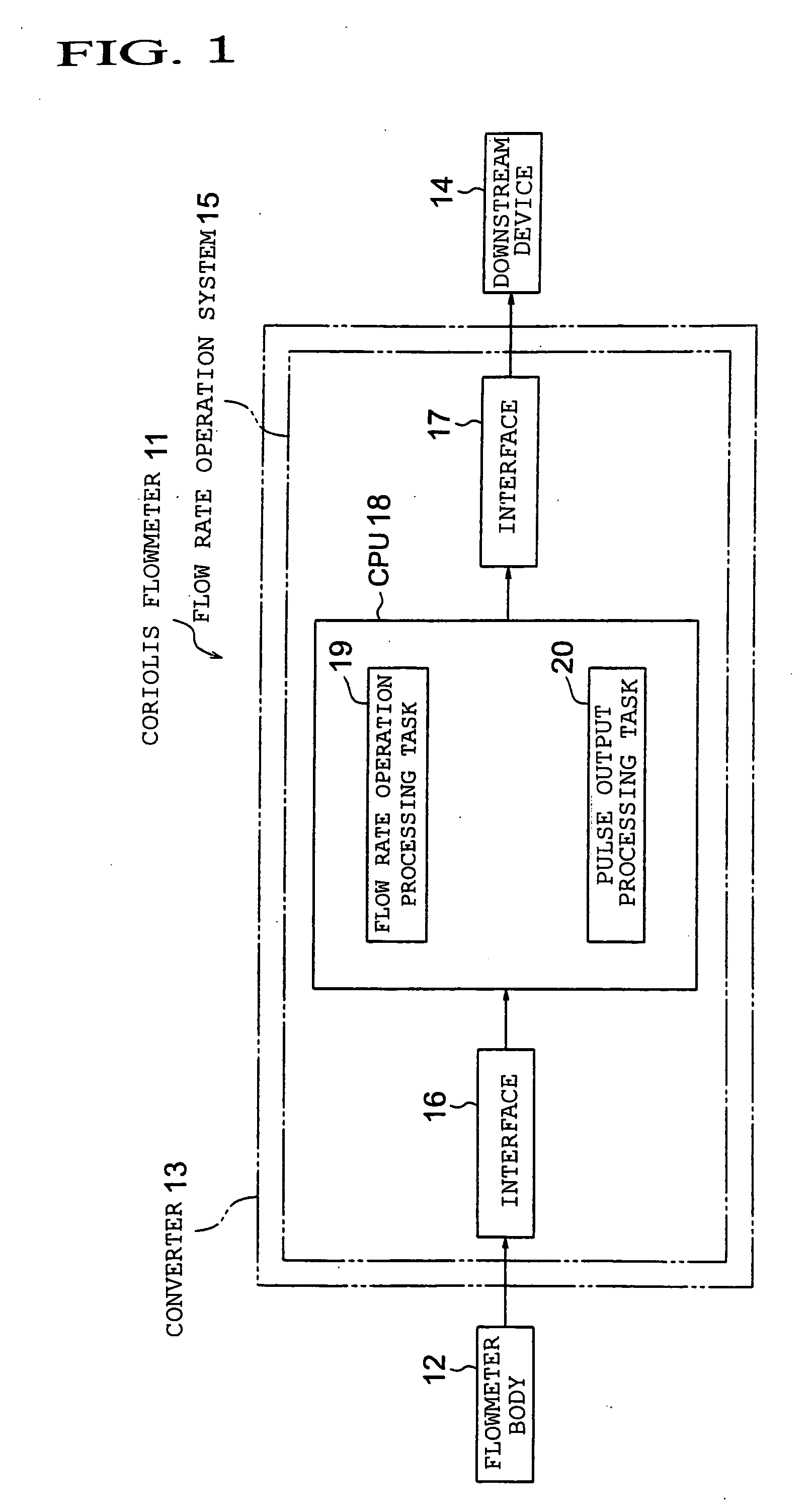
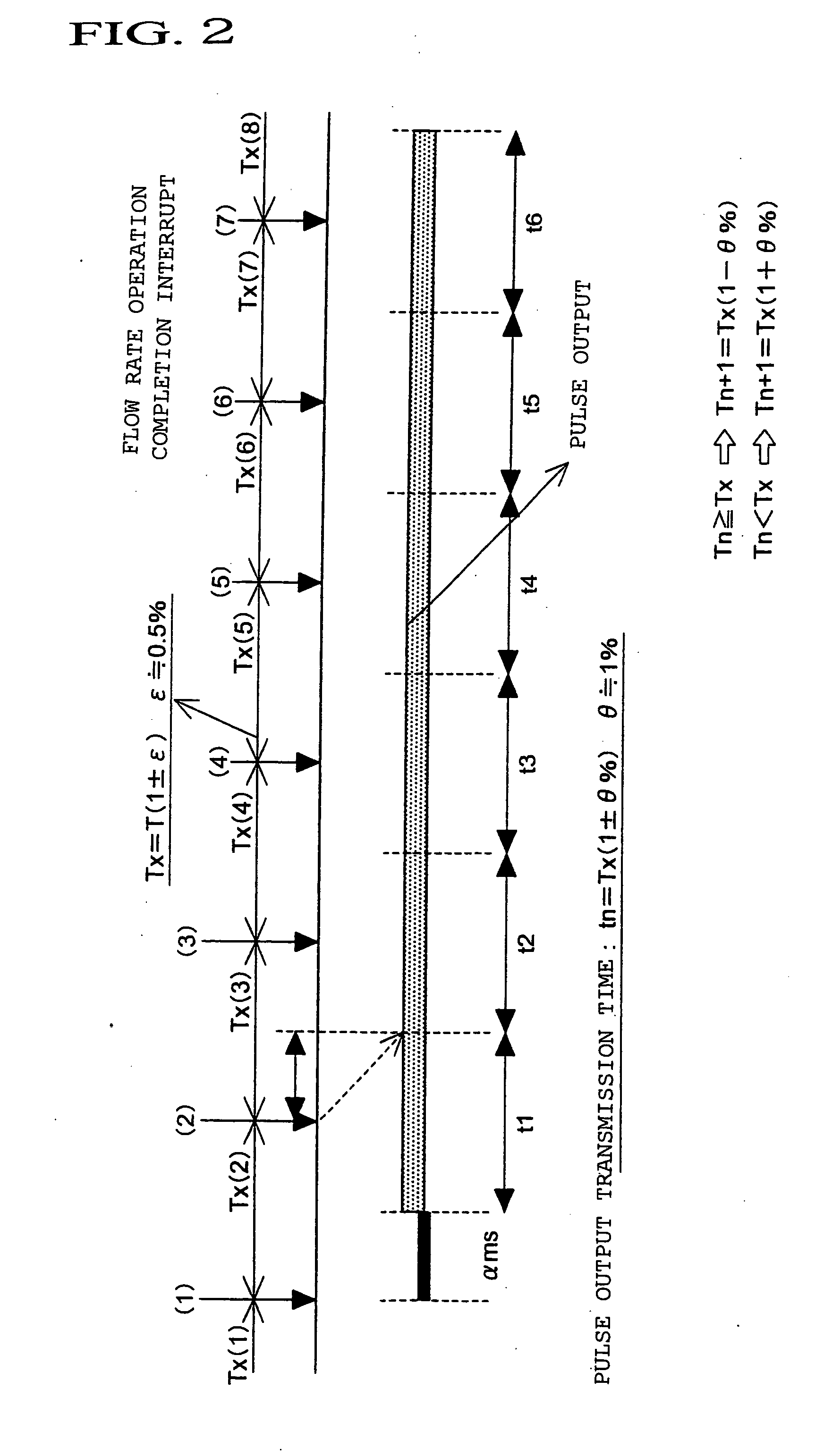
[0038]FIG. 1 is a configuration diagram illustrating a processing method for an operation system according to an embodiment (first embodiment) of the present invention. Further, FIG. 2 is a control explanatory diagram illustrating control of a flow rate operation system.

[0039]Referring to FIG. 1, a Coriolis flowmeter 11 includes a flowmeter body 12, which is publicly well-known, and a converter 13, which is related to the present invention. The Coriolis flowmeter 11 is connected to a downstream device 14 via the converter 13, and is configured to output / transmit a pulse signal to the downstream device 14. Note that, in a case where the downstream device 14 is, for example, a display device, the downstream device 14 as the display device may be included in the configuration of the Coriolis flowmeter 11 by integrating into the converter 13.

[0040]The converter 13 includes a flow rate operation system 15 (with regard to other configurations which have general functions, illustrations an...

second embodiment

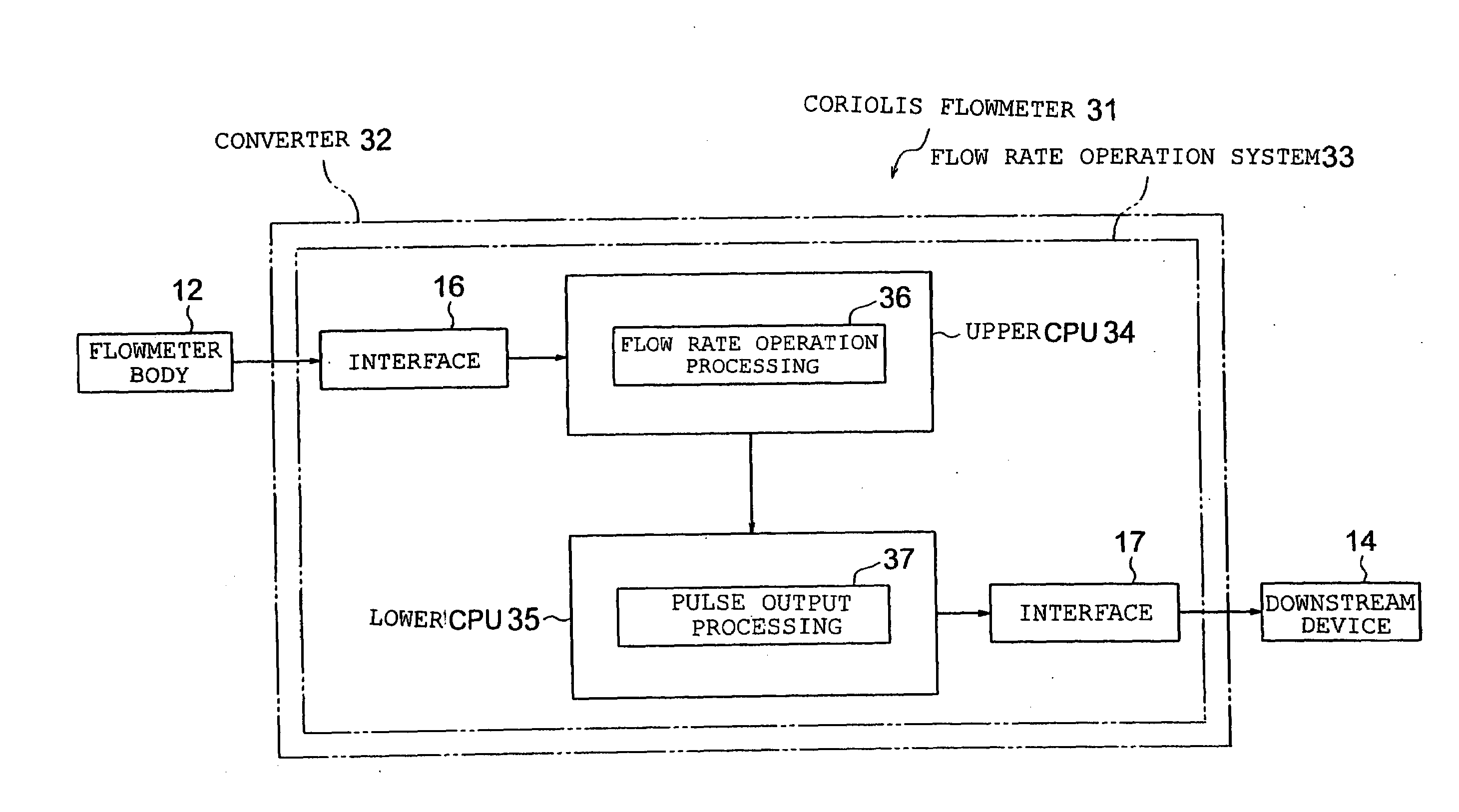
[0063]FIG. 3 is a configuration diagram illustrating a processing method for an operation system according to another embodiment (second embodiment) of the present invention. Further, FIG. 4 is a diagram illustrating a configuration of an upper CPU; FIG. 5 is a diagram illustrating a configuration of a lower CPU; and FIGS. 6 and 7 are control explanatory diagrams illustrating control of a flow rate operation system.

[0064]Referring to FIG. 3, a Coriolis flowmeter 31 includes the flowmeter body 12, which is publicly well-known, and a converter 32, which is related to the present invention. The Coriolis flowmeter 31 is connected to the downstream device 14 via the converter 32, and is configured to output / transmit a pulse signal to the downstream device 14. Note that, as in the first embodiment described above, in a case where the downstream device 14 is, for example, a display device, the downstream device 14 as the display device may be included in the configuration of the Coriolis f...


PUM


Abstract

Provided is a processing method for an operation system which performs operation processing in accordance with a detection amount detected by detection means and pulse output processing in which an operation result from the operation processing is transmitted as a pulse output, including: controlling transmission of the pulse output performed in the pulse output processing to make the transmission of the pulse output asynchronous with a timing of an end of the operation processing; and transmitting, by repeating the controlling, a pulse train having time-series continuity.

Description

TECHNICAL FIELD[0001]The present invention relates to a processing method for an operation system, and more particularly, to a processing method which enables an operation system to perform processing of transmitting pulse outputs as a pulse train having time-series continuity. In addition, the present invention relates to a flow rate converter, which adopts the processing method for an operation system, and a Coriolis flowmeter provided with the flow rate converter.BACKGROUND ART[0002]For example, as a technology relating to pulse signal output processing performed by a converter of a Coriolis flowmeter, there is known a technology disclosed in JP 2002-133572 A by the applicant of the present invention.[0003]In JP 2002-133572 A, the Coriolis flowmeter includes a flowmeter body and a converter. A detection value from the flowmeter body is input to the converter. When the detection value is input to the converter, a microprocessor performs operation processing and other processing in...

Claims


Application Information

Patent Timeline
IPC IPC(8): G08C19/16
CPCG01F15/06G01F1/8436
Inventor KITAMI, HIROKAZUSAITOH, SHUNJISHIMADA, HIDEKI
Owner OVAL CORP
Why Eureka
Try Eureka