
Optical recording method

Active Publication Date: 2007-10-18
RICOH KK
View PDF24 Cites 0 Cited by
  • Summary
  • Abstract
  • Description
  • Claims
  • Application Information

AI Technical Summary

Benefits of technology

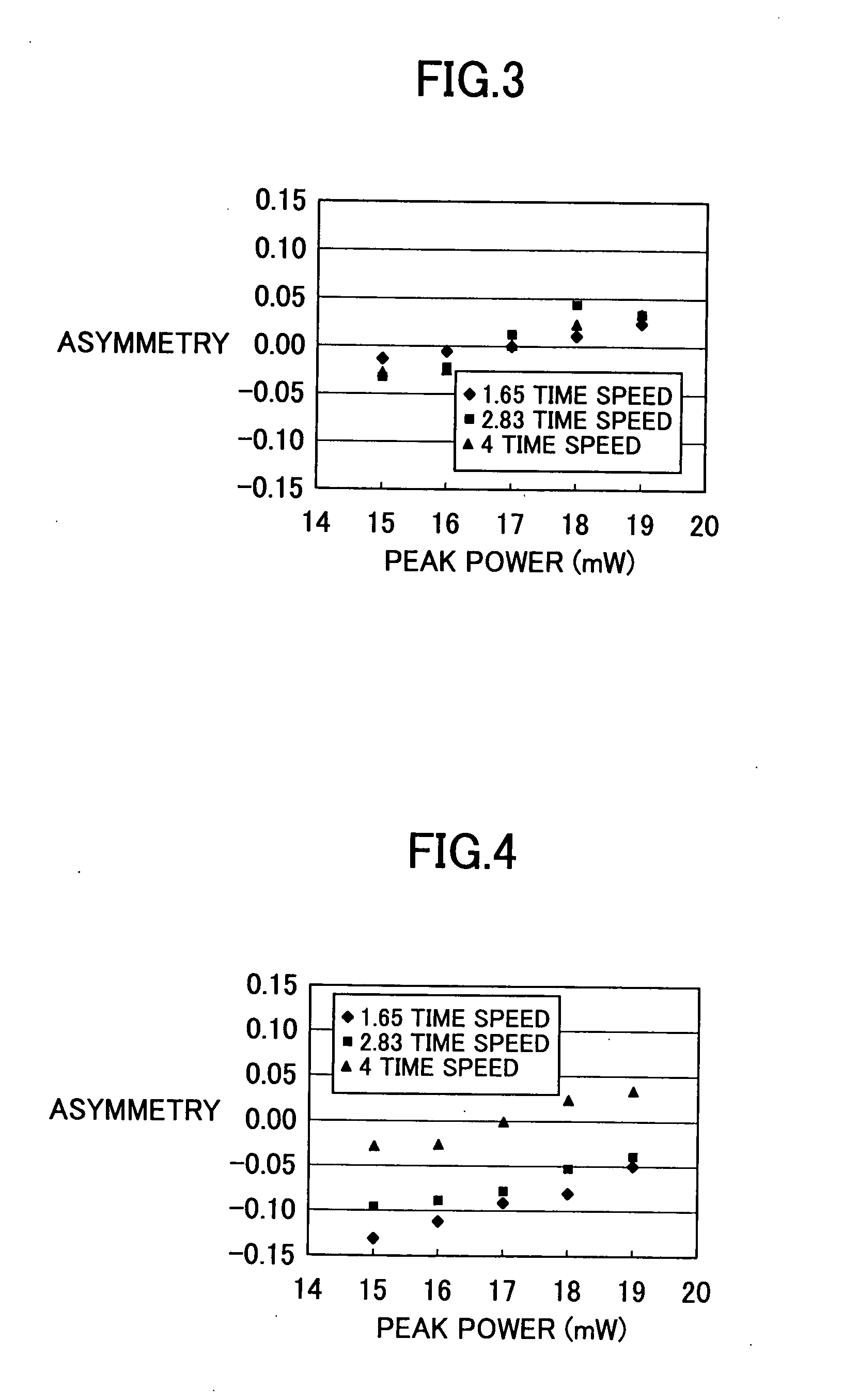
[0015] Another object of the present invention is to provide a recording method suitable for CAV recording onto a phase change optical recording medium on which recording at, a low linear velocity can be achieved in a low peak power range while recording at a high linear velocity can be achieved in a high peak power range, wherein, in the CAV recording, the linear velocity changes continuously from the low linear velocity through the high linear velocity throughout a range from an inner circumferential part through an outer circumferential part of the medium. A further particular object of the present invention is to provide a recording method advantageous for an optical recording medium which is a rewritable DVD, having the maximum linear velocity of 4 time speed (4×) of DVD, and, also, backward compatible with a disk drive which performs recording at a linear velocity in a range between 1 time speed (1×) and 2.4 time speed (2.4×).

Problems solved by technology

When a medium configuration and a recording material of a phase change optical recording medium are optimized for providing a medium suitable for high linear velocity recording, it is difficult to obtain a satisfactory performance throughout a wide range of linear velocity only by means of pulse interval control of light pulse applied.
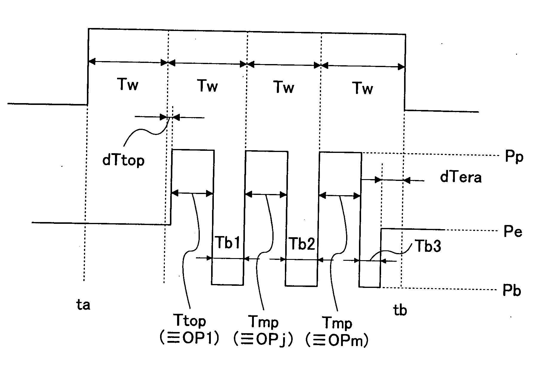
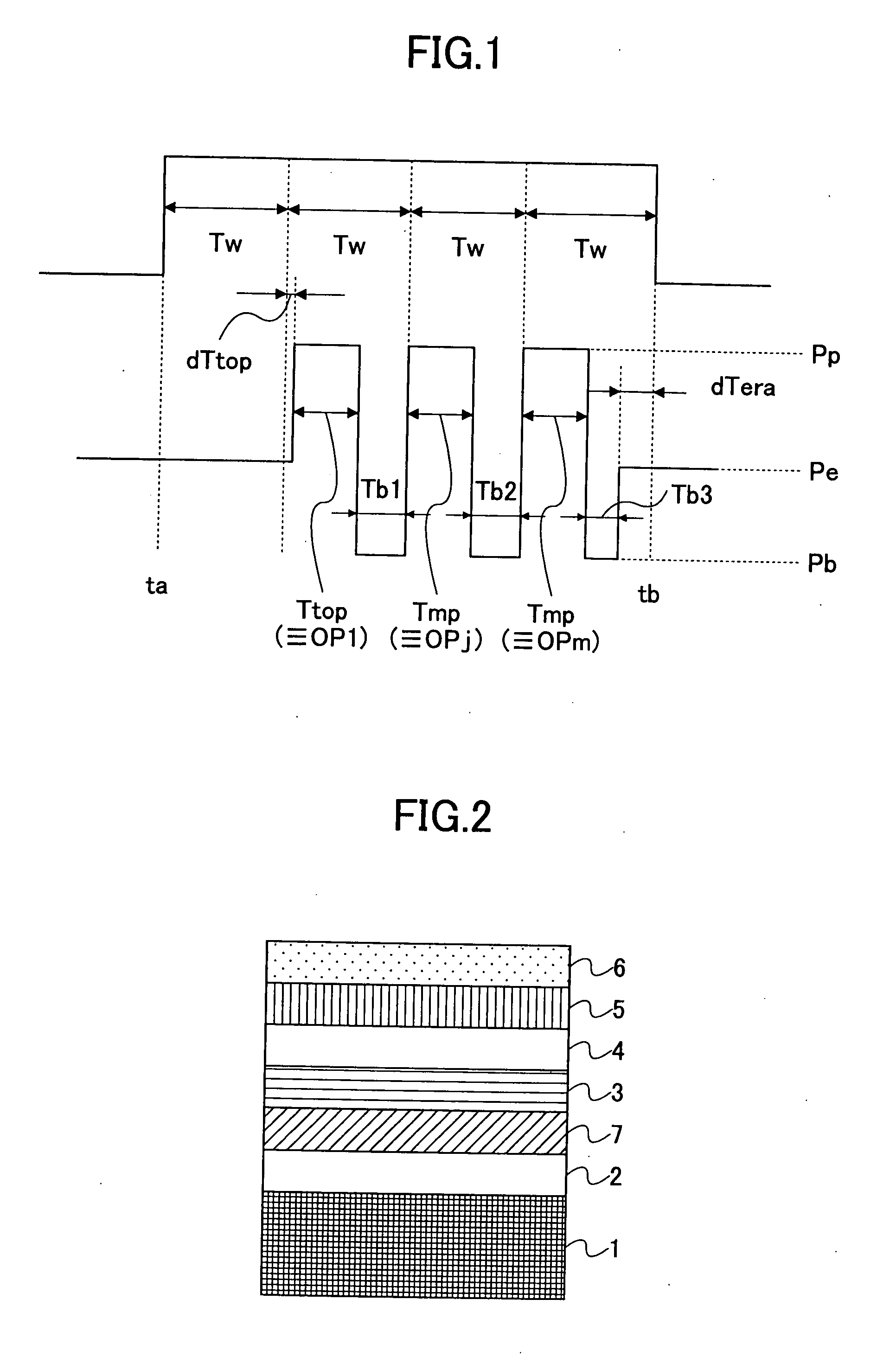
However, according to a conventional method, unless control is made precisely for each of various recording line velocities on a top peak power application starting time of pulse series to be applied upon recording a predetermined length of mark on a recording medium, ‘asymmetry’ which is an item of recording characteristics may not lie within a required range.
If so, recorded data thus obtained may not be reproduced properly therefrom, and, thus, data error may occur.
Furthermore, along therewith, as a margin with respect to the peak power should be narrowed, and, thus, recording signal quality may tend to decrease further.

Method used


Image

  • Optical recording method
  • Optical recording method
  • Optical recording method

Examples


embodiment 1

[0096] First, a phase change optical recording medium was produced as follows:

[0097] By using a substrate made of polycarbonate with a thickness of 0.6 mm, having a groove pitch of 0.74 μm, a groove width of 0.25 μm and a groove depth of 25 nm for recording record marks therein, each layer was laminated thereon by a spattering method.

[0098] First, a target of ZnS:SiO2=80:20 (molar %) was used, and a lower protective layer with a film thickness of 54 nm was provided.

[0099] Then, a target of a composition of Ge:Ag:In:Sb:Te=3.8:0.3:3.5:72:20.4 was used, and a phase change recording layer with a film thickness of 12 nm was provided.

[0100] Then, a target of composite oxide of ZrO2.Y2O3 (3 molar %)·TiO2 (20 molar %) was used, and an interface layer with a film thickness of 3 nm was provided.

[0101] Then, a target of ZnS:SiO2=80:20 (molar %) was used, and an upper protective layer with a film thickness of 11 nm was provided.

[0102] Then, after an SiC layer (sulfating-avoiding layer) wi...

embodiment 2

[0113] By using the optical recording medium same as that in the above-mentioned embodiment 1, recording / playback was performed under the conditions shown in Table 2 below. The other conditions were same as those in the embodiment 1. The maximum linear velocity was 2.40 time speed (8.4 m / s), the minimum linear velocity was 1.0 time speed (3.5 m / s) and the intermediate linear velocity was 1.7 time speed (6 m / s).

TABLE 2recordinglinearrecordingvelocitylinear(timevelocityParameterspeed)(m / s)dTtopTtopTmpdTeraε1.03.5Tw / 6Tw / 6 +Tw / 6 + 6 ns−Tw / 60.476 ns1.76Tw / 600.502.408.4Tw / 6Tw / 60.53

[0114]FIG. 5 shows a result of evaluation of jitter and asymmetry in the recording characteristics thus obtained with the peak power of 15 mW. As shown, satisfactory characteristics were obtained approximately without depending on the linear velocity. In the above-mentioned linear velocity range, the top pulse beginning time (peak power application starting time of the pulse top: dTtop) was determined by a fix...

embodiments 3 through 5

[0115] In an embodiment 4 of the present invention, by using the same optical recording medium as that in the above-mentioned embodiment 1, when the linear velocity was changed from 3.5 m / s through maximum 14 m / s at a rate of 0.5 m / s; the linear velocity at which the reflectance started dropping was around 10.5 m / s (see the embodiment 4 in Table 3 below).

[0116] Then, optical recording media were produced in the same way as that in the embodiment 1 except that the material of the recording layer was changed to compositions of Ag:In:Sb:Te:Ge=0.5:5:68:24.5:2 (embodiment 3 of the present invention) and Ag:In:Sb:Te:Ge=0.3:4:73:19.7:3 (embodiment 5 of the present invention), respectively. Then, when measurement was performed as in the embodiment 4 described above, the reflectance started dropping around 8.5 m / s and 11.5 m / s for the embodiments 3 and 5, respectively, as shown in Table 3.

TABLE 3reflectancedroppingDOW 1 jitter (%)start linear2.4 timevelocity4 time speedspeedembodiment 3 8...


PUM


Abstract

An optical recording method of recording information to a phase change optical recording medium with alternate application of peak power and bias power in a pulse manner and with changing a pulse application. interval continuously from an inner part through an outer part of the recording medium with an interval proportional to a window width Tw and a fixed interval, comprising the step of starting a top peak power application interval with a delay from a data input pulse signal starting time for a target mark length nTw, where n denotes an integer in a range between 3 and 14, with changing the delay in proportion to the window width Tw with changing a proportionality factor discretely with respect each linear velocity.

Description

BACKGROUND OF THE INVENTION [0001] 1. Field of the Invention [0002] The present invention relates to a recording method for a phase change optical recording medium, and, in particular, to a recording method for a rewritable DVD medium. [0003] 2. Description of the Related Art [0004] Recently, a large size of image data is handled, and, therefore, a recording medium therefor thus having a larger storage capacity is demanded. Further, it is also demanded to record such a large size of image data in the recording medium and reproduce the same therefrom at high speed. A technique of phase change optical recording medium is applied to a CD or DVD rewritable recording medium, and has been wide used since it has characteristics of having a large storage capacity and has a high compatibility with a ROM. Especially, high speed recording / playback has been achieved with CD-ROM or CD-R, and, as a result, a phase change optical recording medium is also demanded to have a performance such that hi...

Claims


Application Information

Patent Timeline
IPC IPC(8): G11B7/00G11B7/0045G11B7/006G11B7/24G11B7/125
CPCG11B7/0062
Inventor YUZURIHARA, HAJIMEABE, MIKIKODEGUCHI, HIROSHIHIBINO, EIKOMIURA, HIROSHIITO, KAZUNORIABE, MICHIHARU
Owner RICOH KK
Learn More