
Street lamp

a technology of street lamps and lampshades, applied in the field of street lamps, can solve the problems of reducing the use of conventional orienteering means, such as signs and guideposts, and reducing the difficulty or the inability to use them

Inactive Publication Date: 2009-11-26
HON HAI PRECISION IND CO LTD
View PDF2 Cites 1 Cited by
  • Summary
  • Abstract
  • Description
  • Claims
  • Application Information

AI Technical Summary

Benefits of technology

The present patent is about a street lamp that can indicate its direction at the geographic location where it is placed. The lamp includes a cover, a light pervious member, a light source, and a pivoting compass indicator. The compass indicator is mounted on the light pervious member and includes a symbol that represents the direction. The lamp can be used in various locations and does not require power or assistance from other sources. The technical effect of the invention is to provide a convenient and reliable way to indicate direction for users, even in areas where other assistance is not available.

Problems solved by technology

Conventional means of orienteering, such as signs and guideposts, may be rendered difficult or impossible to use by power outages or bad weather conditions.

Method used


Image

  • Street lamp
  • Street lamp
  • Street lamp

Examples


first embodiment

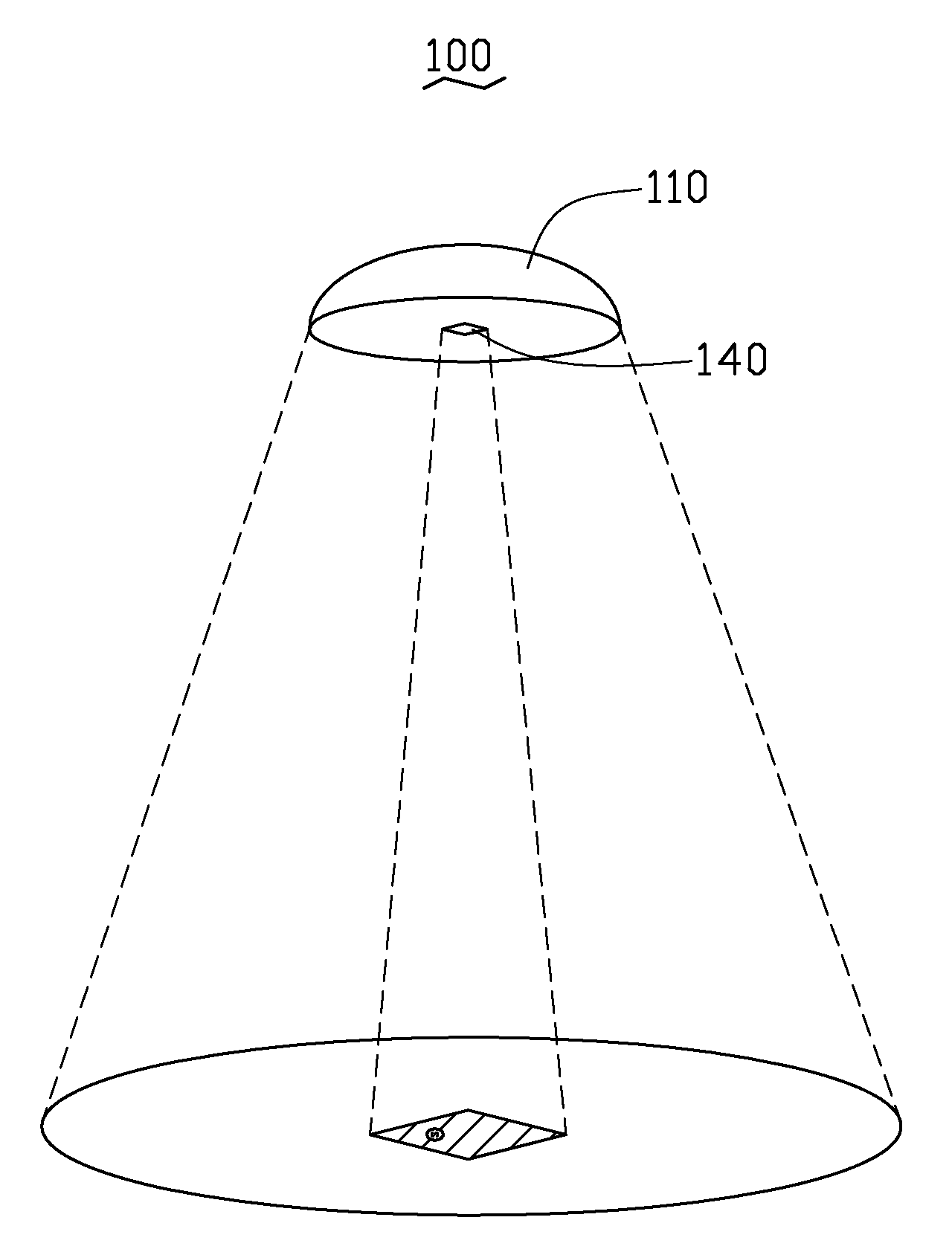
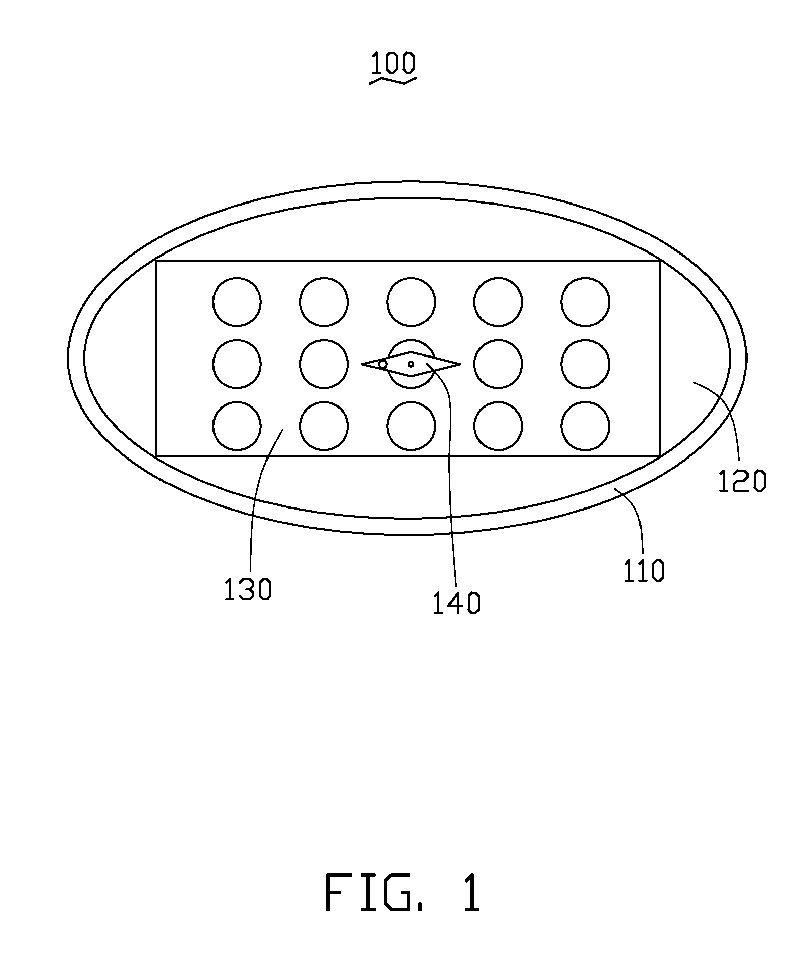
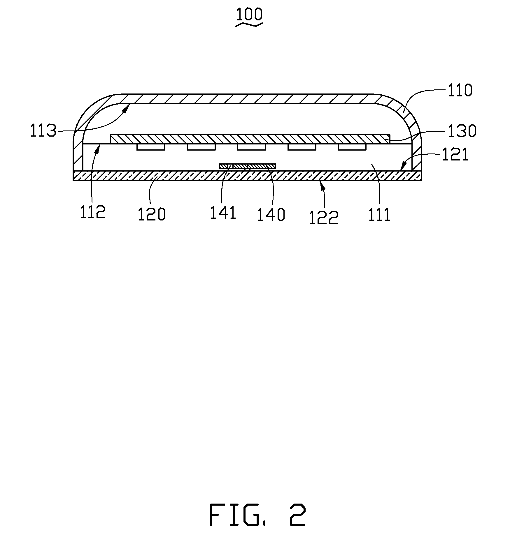
[0014]Referring to FIGS. 1 to 4, a street lamp 100 for being stalled on the ground, in accordance with a first embodiment, includes a cover 110, a light pervious member 120, a light source 130 and a pivoting compass indicator 140.

[0015]The cover 110 defines a cavity 111 for receiving the light source 130. The light pervious member 120 includes a light incident surface 121 and an opposite light emitting surface 122 for facing the ground. The light source 130 is arranged opposite to and facing the light incident surface 121. The light pervious member 120 may be a plate or a mask of light pervious materials, such as glass or plastic. The light source 130 is mounted in the cover 110 and supported by a supporting member 112. The supporting member 112 may be a plate, a shaft or other structure. Here, the supporting member 112 is a shaft fixed on the cover 110. Alternatively, the light source 130 may be mounted on the inner top surface 113 of the cover 110.

[0016]The pivoting compass indica...

second embodiment

[0019]Referring to FIG. 5, a pivoting compass indicator 240 of a street lamp (not shown), in accordance with a second embodiment is shown, differing from the previous embodiment only in the inclusion of a double-color lens 242. The double-color lens 242 is arranged under the indicator 241 and is rotatable together therewith. The double-color lens 242 includes a first color lens portion and a second color lens portion, positionally corresponding to the north and south ends, respectively. The double-color lens 242, when projected with the image of the compass indicator 240, provides an even more easily recognized indication of the compass direction.

[0020]It should be understood that, in addition to the representative colors disclosed, the ends of the pivoting compass indicator 240 can additionally bear symbols indicating the appropriate compass direction, such symbols being applied to a surface of the double-color lens 242 beyond the indicator 241 and being light-impervious material. ...


PUM


Abstract

An exemplary street lamp for being stalled on the ground includes a light source, a light pervious member and a direction indicator. The light pervious member includes a light incident surface and an opposite light emitting surface for facing the ground. The light source is arranged opposite to the light incident surface. The direction indicator is arranged on the light pervious member for projecting the shadow thereof on the ground to indication a direction at the geographic location of the street lamp.

Description

BACKGROUND[0001]1. Technical Field[0002]The present disclosure relates to a light source module, and particularly to a street lamp capable of indicating a direction at the geographic location thereof.[0003]2. Discussion of Related Art[0004]With developments in technology, light source modules are providing more varied applications with more convenience provided for users.[0005]Conventional means of orienteering, such as signs and guideposts, may be rendered difficult or impossible to use by power outages or bad weather conditions. Additionally, there is a consistent possibility that orientation may be needed in a location without such assistance.[0006]Therefore, what is needed is a street lamp capable of overcoming the described limitations.BRIEF DESCRIPTION OF THE DRAWINGS[0007]Many aspects of the present street lamp can be better understood with reference to the following drawings. The components in the drawings are not necessarily to scale, the emphasis instead being placed upon ...

Claims


Application Information

Patent Timeline
Patent Type & Authority Applications(United States)
IPC IPC(8): F21V33/00
CPCF21S8/08F21V33/00Y02B20/72G01C17/22F21W2131/103
Inventor WU, CHIA-YING
Owner HON HAI PRECISION IND CO LTD
Learn More