Wireless communication device and method of displaying wireless communication state

a wireless communication and wireless communication technology, applied in the field of wireless communication devices and a method of displaying a wireless communication state, can solve the problems of difficult for users to search for the installation location of the device unit, difficult to solve, and inability to display a state of data communication with a host device in real time in the device unit for performing wireless communication using data rate information contained in the communication. achieve the effect of maximizing the effective transfer throughput and high data ra

Inactive Publication Date: 2009-11-26
RENESAS ELECTRONICS CORP
View PDF0 Cites 35 Cited by
  • Summary
  • Abstract
  • Description
  • Claims
  • Application Information

AI Technical Summary

Benefits of technology

[0016]FIG. 1 shows an example of the operation and effect of a wireless communication device and a method of displaying a wireless communication state according to an exemplary embodiment of the present invention. FIG. 1 shows a case where a data transfer 31 is performed between a wireless communication device unit 1a and a wireless communication host device 2. First, the wireless communication device unit la displays contents as shown in a light emitting diode (LED) image 19a, for example, based on data rate information contained in a communication packet obtained by the data transfer 31. In this case, the LED image 19a indicates that the data transmission rate for the data transfer 31 is low. Accordingly, a user of the wireless communication device unit la carries out a movement 32 of the position of the wireless communication device unit, thereby moving the wireless communication device unit 1a to an installation location of a wireless communication device unit 1b. After that, a data transfer 33 is performed between the wireless communication device unit 1b and the wireless communication host device 2. Then, the wireless communication device unit 1b displays contents as shown in an LED image 19b based on data rate information contained in a communication packet obtained by the data transfer 33. In this case, the LED image 19b indicates that the data transmission rate of the data transfer 33 is high. In this manner, the wireless communication device unit displays the data rate information contained in the communication packet in the data communication performed at the installation location. Thus, the user of the wireless communication device can recognize the communication state at the installation location. Further, the movement of the wireless communication device unit to an installation location at which the data rate information indicates a higher data rate can be assisted, if necessary.
[0017]According to an exemplary embodiment of the present invention, it is possible to provide a wireless communication device and a method of displaying a wireless communication state, in which a wireless communication device unit visualizes data rate information contained in a communication packet, thereby enabling a user of the wireless communication device unit to search for an optimal location for data communication, and enabling maximization of the effective transfer throughput.

Problems solved by technology

In the technologies disclosed in Japanese Unexamined Patent Application Publication Nos. 2006-238146, 2007-13330, and 2007-288708, however, it is impossible to display a state of data communication with a host device in real time in a device unit for performing wireless communication using data rate information contained in a communication packet as in the WUSB communication.
This causes a problem in that it is difficult for a user to search for an installation location of the device unit at which higher throughput can be obtained.
When a portable electronic device or the like is used as the device unit, however, it is difficult to solve the above-mentioned problem in that the optimal installation location of the device unit with respect to the host device cannot be recognized on the device unit side based on the communication state.
Accordingly, when the installation location of the device unit is moved after the communication state is displayed, the test data needs to be transmitted / received again, which makes it impossible to display the communication state itself in real time in the actual data communication.

Method used


Image

  • Wireless communication device and method of displaying wireless communication state
  • Wireless communication device and method of displaying wireless communication state
  • Wireless communication device and method of displaying wireless communication state

Examples


first exemplary embodiment

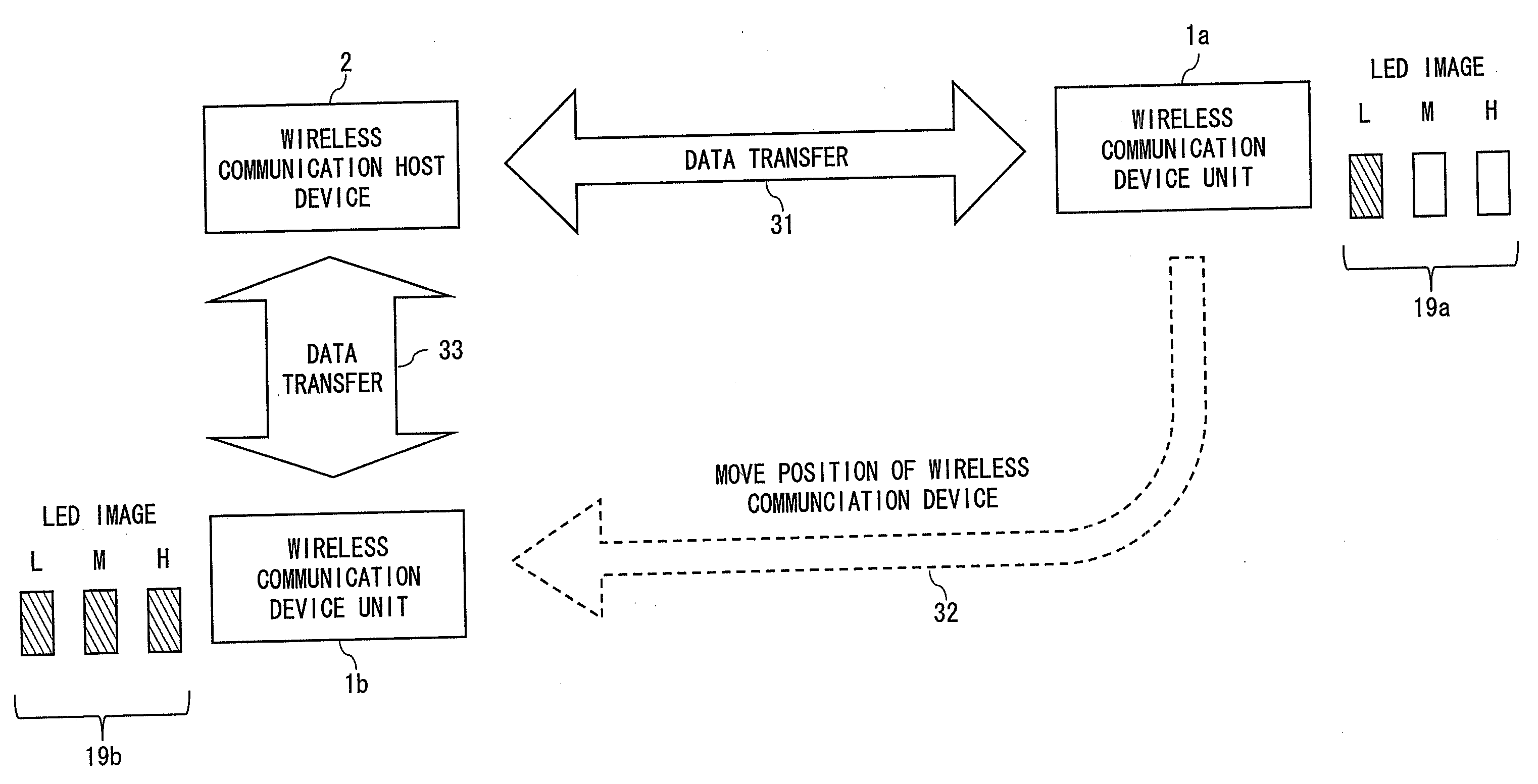
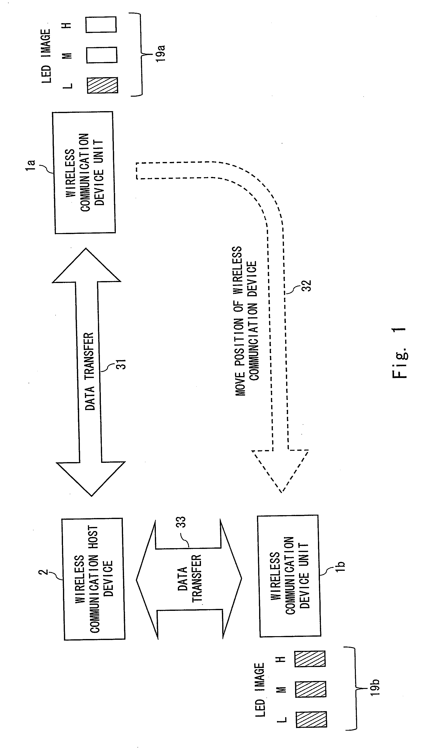
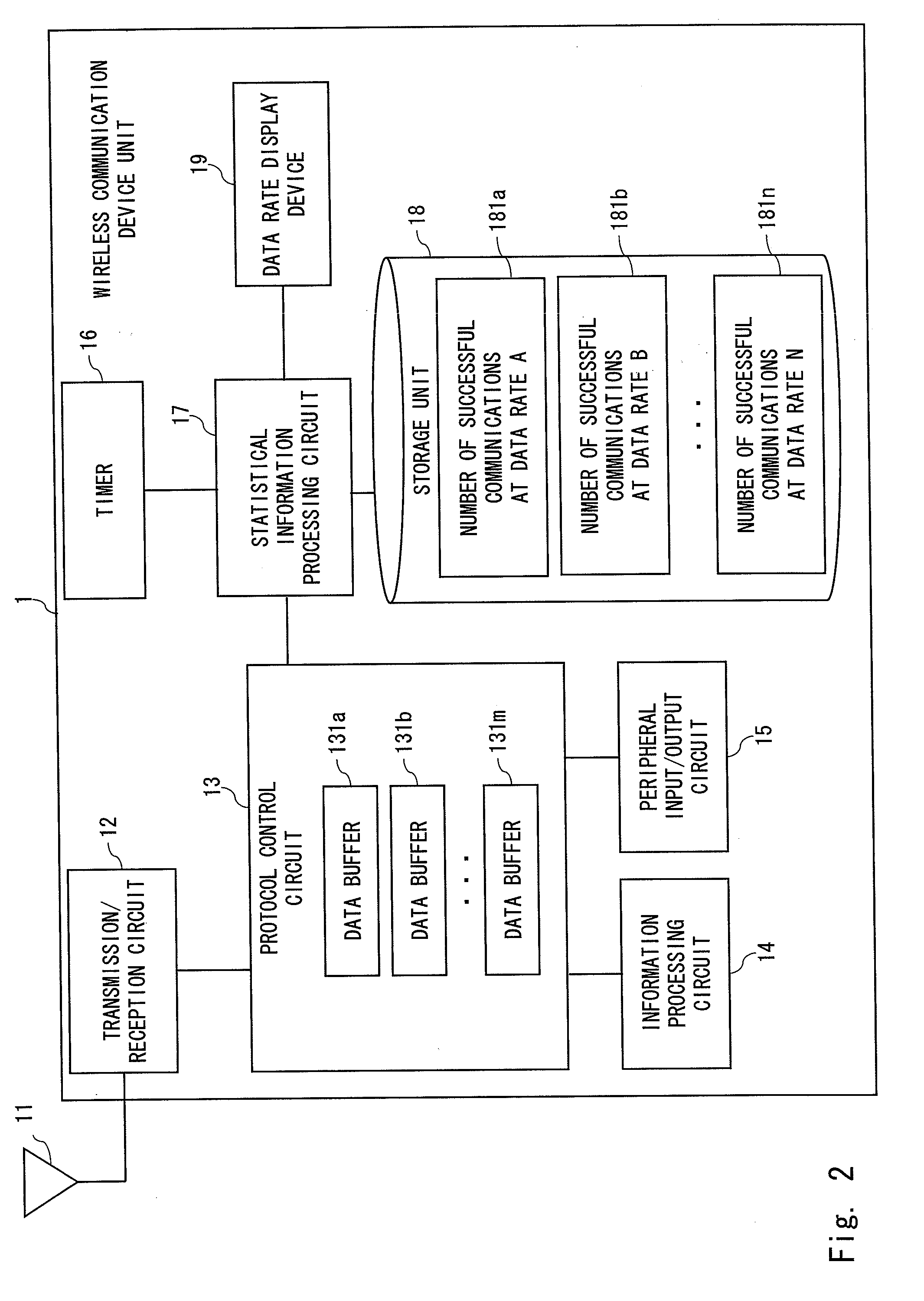
[0029]FIG. 2 is a block diagram showing a configuration of a wireless communication device unit 1 according to a first exemplary embodiment of the present invention. The wireless communication device unit 1 is a portable electronic device such as a portable audio player or a digital camera capable of WUSB communication. Further, the wireless communication device unit 1 performs data communication with a host device (for example, the wireless communication host device 2 of FIG. 2) such as a personal computer capable of WUSB communication. Furthermore, the wireless communication device unit 1 displays information related to a data transmission rate in the data communication (hereinafter, referred to as “data rate information”). The term “data rate information” refers to, for example, information indicating eight kinds of data rates defined in the WUSB standard.

[0030]It is assumed that the wireless communication host device 2 that performs data communication with the wireless communica...


PUM


Abstract

Provided is a wireless communication device that receives at least one communication packet containing data rate information, including: a storage unit that receives the at least one communication packet and stores, in a memory unit, the data rate information contained in the at least one communication packet; a display data generation unit that generates display data rate information to be used for display, based on the data rate information stored in the memory unit; and a display unit that displays the display data rate information generated by the display data generation unit.

Description

BACKGROUND[0001]1. Field of the Invention[0002]The present invention relates to a wireless communication device and a method of displaying a wireless communication state. In particular, the present invention relates to a wireless communication device such as a portable electronic device having a wireless communication function to receive a communication packet containing data rate information, and to a method of displaying a wireless communication state.[0003]2. Description of Related Art[0004]In recent years, many portable electronic devices, such as a portable audio player and a digital camera, have a wired universal serial bus (USB) interface for data communication with a host device such as a personal computer. In this regard, however, every time such a portable electronic device is carried by a user, the portable electronic device has to be connected to or removed from the host device through a USB cable. Additionally, it is necessary to manage the USB cable. Therefore, much at...

Claims


Application Information

Patent Timeline
Patent Type & Authority Applications(United States)
IPC IPC(8): H04B17/00H04B1/3822H04B1/40H04W88/02
CPCH04W28/22
Inventor MATSUMOTO, NAOHIRO
Owner RENESAS ELECTRONICS CORP
Why Eureka
Try Eureka