Method and device for fault location in a system

Inactive Publication Date: 2009-11-26
THALES SA
View PDF11 Cites 15 Cited by
  • Summary
  • Abstract
  • Description
  • Claims
  • Application Information

AI Technical Summary

Benefits of technology

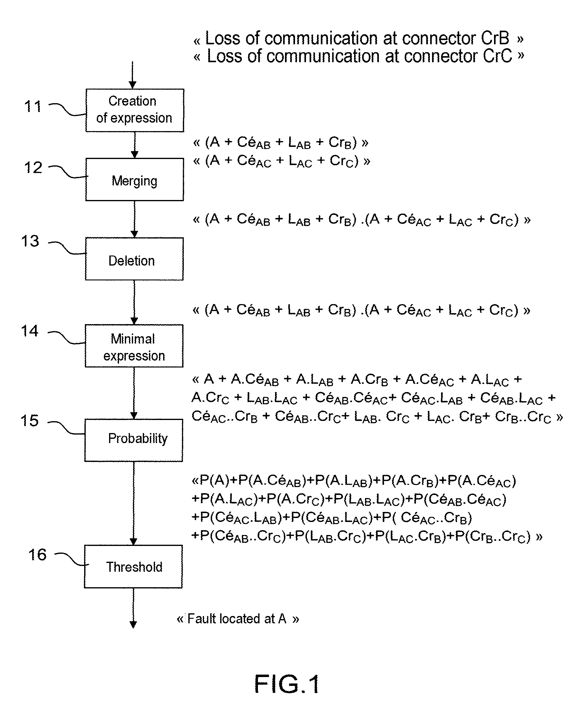
[0041]a threshold from which the failure probability for a group of equipment is neglected without deleting this equipment, such a threshold making it possible to provide a sufficiently precise indication to a maintenance operator without overloading him with too large an amount of indications;
[0042]the system topology, described in a model, to establish the real links between pieces of equipment (which piece of equi

Problems solved by technology

In addition, the methods of fault location process messages coming from equipment that are often erroneous, as these messages contain the names of pieces of equipment defined during development but do not take account of the evolutions and the topology of the system, or as they voluntarily omit part of the potentially faulty equipment due to a lack of space in the message.
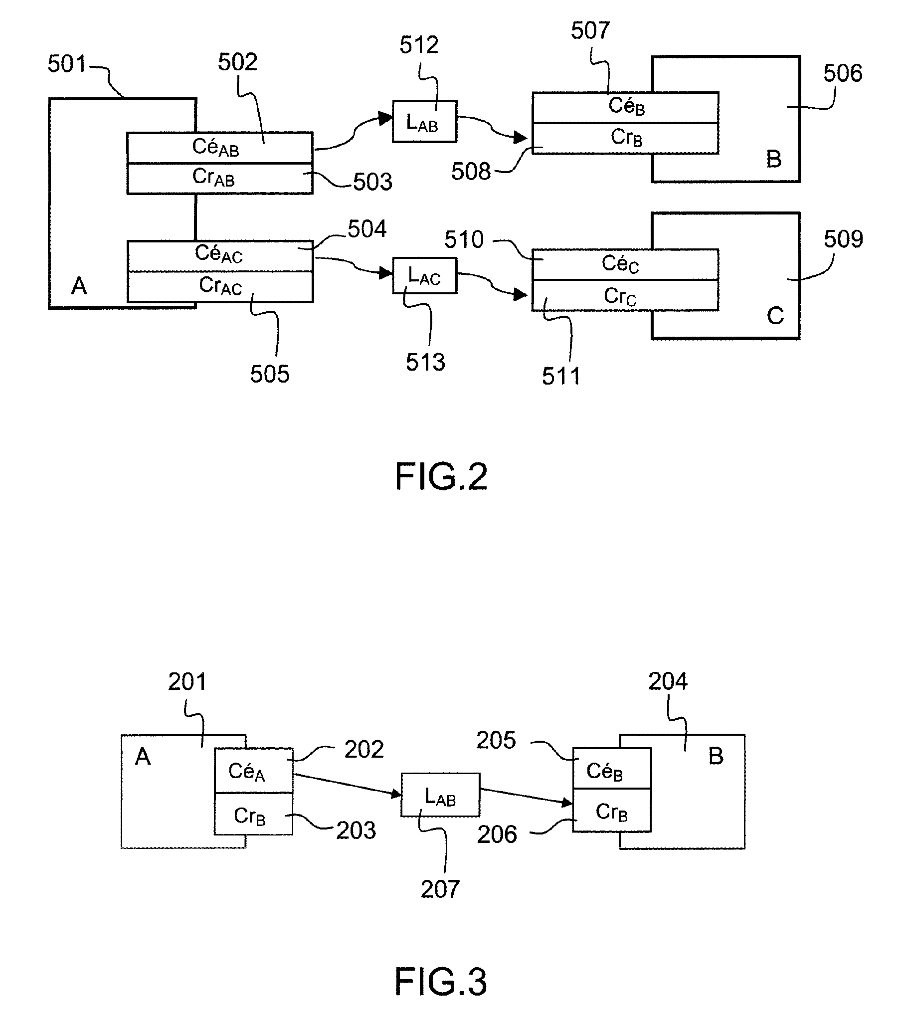
For example, in the case in which a piece of equipment A is communicating with a piece of equipment B and with a piece of equipment C

Method used


Image

  • Method and device for fault location in a system
  • Method and device for fault location in a system
  • Method and device for fault location in a system

Examples


Embodiment Construction

[0052]Aspects of the invention relates to a method and a device for fault location in a system. The system includes a set of elements. The elements are connected in a network. Each element is associated with a failure probability and with a real exposure time.

[0053]Each real piece of equipment communicating on the physical network contains at least one physical component directly connected to the network that will be called the connector: either transmitter connector (the piece of equipment transmits data on the network) and / or receiver connector (the piece of equipment acquires data circulating on the network). Some pieces of equipment serve to transmit the data on the network. They are called “switches” and have transmitter and receiver connectors. The relation between a transmitter connector of one piece of equipment and a receiver connector of another piece of equipment is called a “link”. A link may be broken down into “sublinks” and into connectors connected directly to each o...


PUM


Abstract

The invention relates to a method and a device for locating a fault in a system. The system includes a set of elements. The elements are connected in a network. Each element is associated with an operational status and a probability of failure. The method according to an embodiment of the invention includes, for each of the elements having a status indicating a malfunction, denoted as a defective element, the creation, from the system topology, of an expression comprising terms corresponding to functional elements connected to said defective element. If several expressions have been created in the preceding step, then merge expressions having at least one term in common. For each expression, delete terms in the expression corresponding to elements having a “healthy” status. Calculate a minimal expression from the preceding expression. Calculate failure probabilities for selected members of the minimal expression based on failure probabilities of the corresponding elements. Calculate the location of the fault to the elements corresponding to the members of the minimal expression for which the ratio of failure probabilities to exposure time is greater than a threshold.

Description

CROSS-REFERENCE TO RELATED APPLICATION[0001]The present application claims the benefit of French Patent Application No. 08 02589, filed May 13, 2008, which is hereby incorporated by reference in its entirety.TECHNICAL FIELD[0002]The invention relates to the maintenance of a set of equipment, such as the set of aviation equipment situated in the cabin or on the passenger side of a civil or military aircraft which fulfils, for example, the diverse functions necessary for completing a flight. The invention relates more specifically to the location of a fault in such a set of equipment.BACKGROUND OF THE INVENTION[0003]These pieces of equipment communicate with each other and with the surroundings through a physical network. This communication network, associated with a set of equipment, is known by the name ADCN, for Avionics Data Communication Network.[0004]The fault location is based on a reliable diagnosis of all or part of this set of equipment. Such a diagnosis must take into accou...

Claims


Application Information

Patent Timeline
IPC IPC(8): G06F11/28
CPCG06F11/008G05B23/0251
Inventor FOURNIER, FRANCOISSANNINO, CHRISTIANBAILLY, CARINE
Owner THALES SA
Why Eureka
Try Eureka