Recording apparatus
a recording head and recording material technology, applied in the field of recording devices, can solve the problems of unstable gap between the recording surface of the recording material, deterioration of the parallelism of the recording head and the ink ejection surface of the recording head, and the quality of the recording execution is reduced, so as to reduce the problem of deterioration
- Summary
- Abstract
- Description
- Claims
- Application Information
AI Technical Summary
Benefits of technology
Problems solved by technology
Method used
Image
Examples
embodiment 1
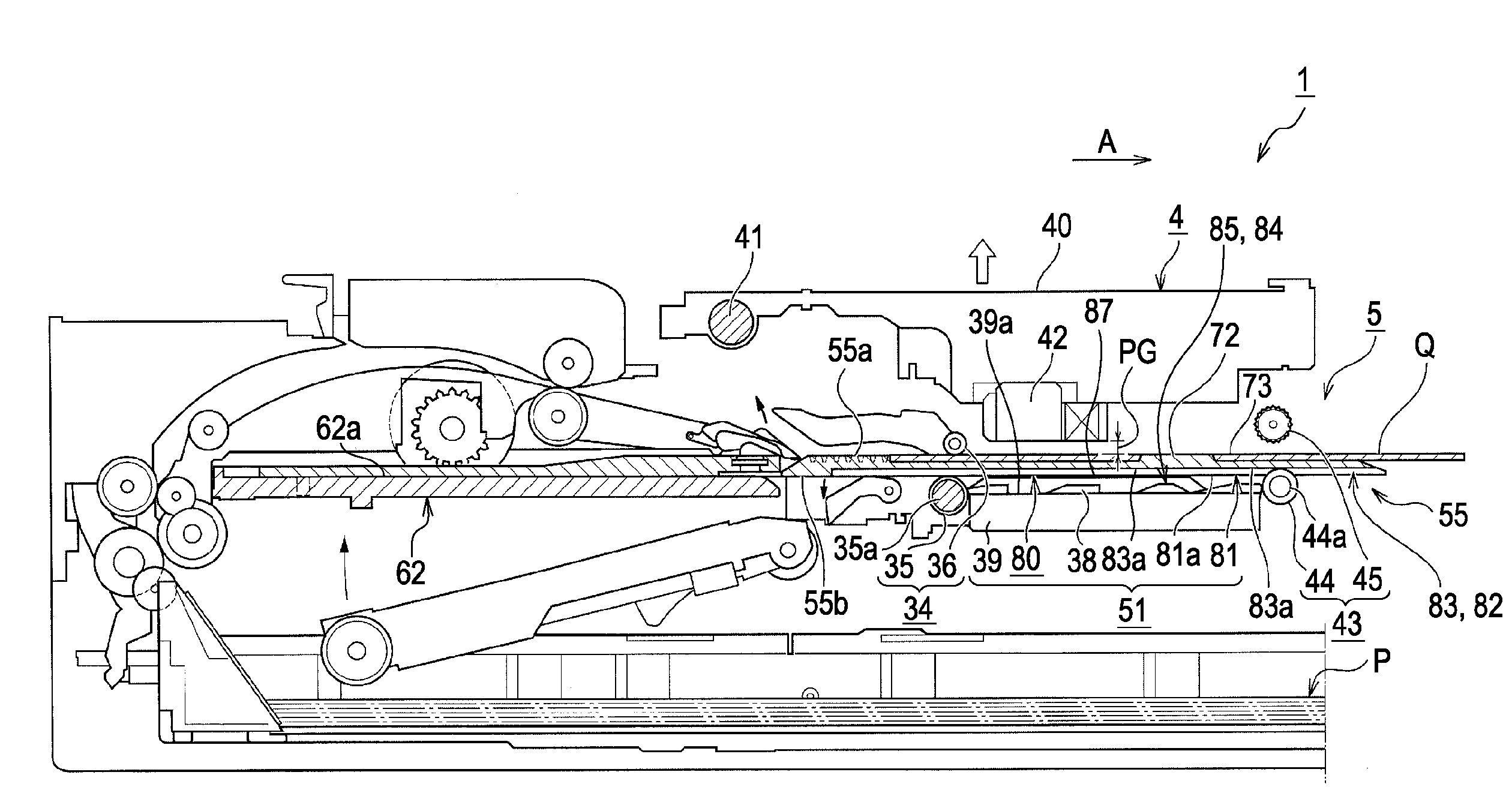
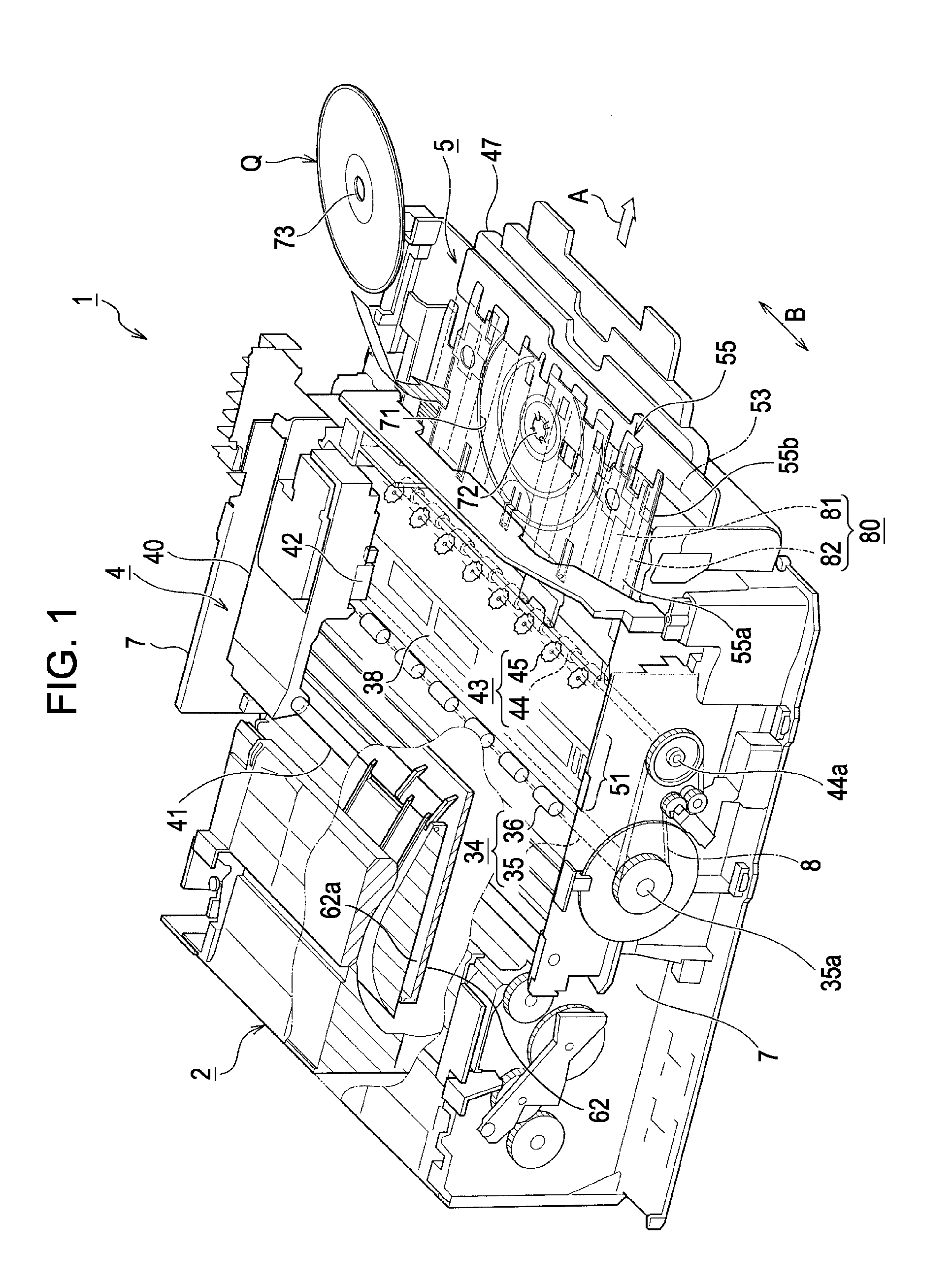
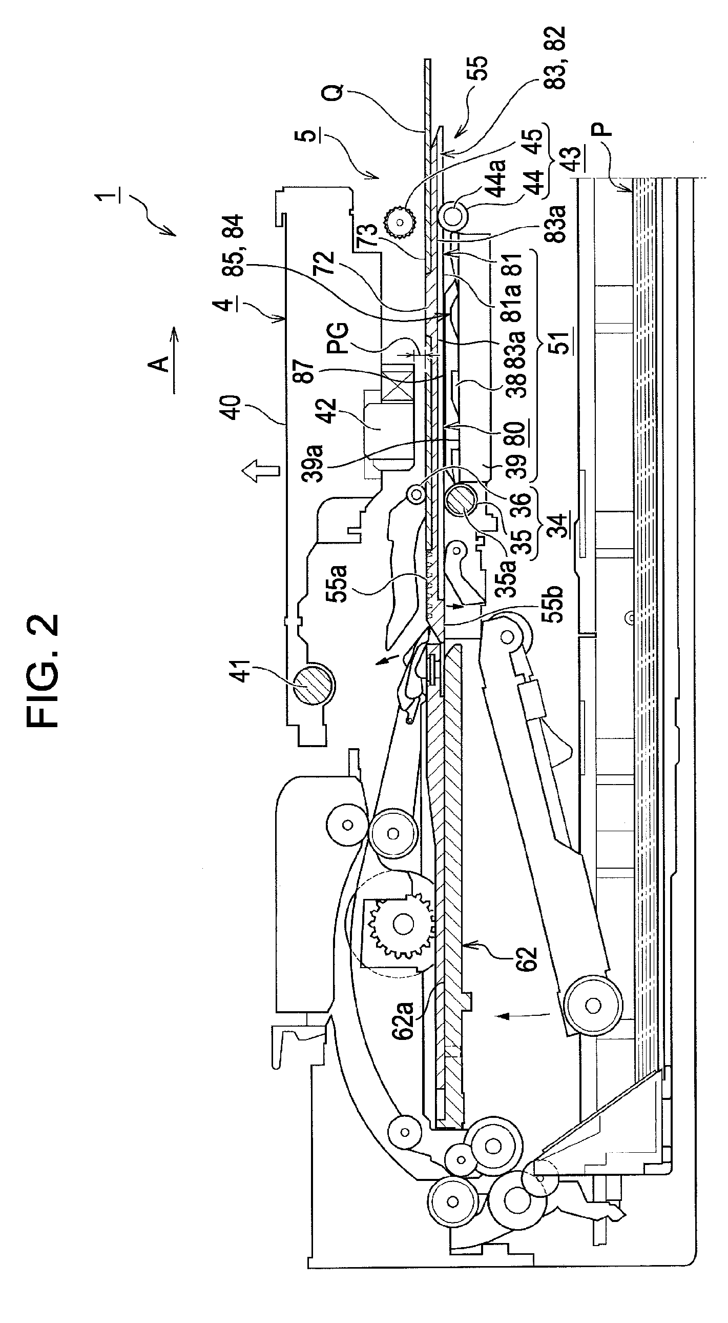
[0044]Next, the structure and working of the recording material transport device 5 in the ink jet printer 1 according to this embodiment will be specifically described with reference to the drawings. FIG. 3 is a perspective view showing the recording material transport device of this embodiment with the holding tray located at the set position. FIG. 4 is a side sectional view showing the recording material transport device with the holding tray located at the recording execution area. FIG. 5 is a plan view of the recording material transport device with the holding tray located at the recording execution area. FIG. 6 is a sectional view taken along line VI-VI of FIG. 5, part thereof enlarged. FIG. 7 is a sectional view taken along line VII-VII of FIG. 5, part thereof enlarged. FIG. 8 is a perspective view showing the upper surface (one surface) of the holding tray. FIG. 9 is a perspective view showing the lower surface (the other surface) of the holding tray.
[0045]The recording mate...
embodiment 2
[0056]Although the recording apparatus 1 according to the invention is based on the above-described configuration, of course, modifications, omissions, and so forth may be made without departing from the scope of the invention.
[0057]FIG. 10 is a plan view showing another embodiment in which the posture maintainer has a different configuration. FIG. 11A is a sectional view taken along line XIA-XIA of FIG. 10. FIG. 11B is a sectional view taken along line XIB-XIB of FIG. 10.
[0058]As shown in FIGS. 10, 11A, and 11B, the posture maintainer 84 can include supporting disks 90 provided on parts of the roller driving shaft 44a near the ejection driving rollers 44. In the embodiment shown in FIGS. 10, 11A, and 11B, slits 91 for receiving the supporting disks 90 are provided near the edges of the grooves 83 in the lower surface 55b of the holding tray 55. The bottom surfaces 91a of the slits 91 are slightly shallower than the bottom surfaces 83a of the grooves 83, that is, the bottom surfaces...
embodiment 3
[0060]FIG. 12 is a vertical sectional view showing still another embodiment in which the posture maintainer has a different configuration taken along the nip of the ejection roller. As shown in FIG. 12, between the roller driving shaft 44a of the ejection driving rollers 44 and each of the top surfaces 81a of the projections 81 on the lower surface 55b of the holding tray 55, a space 94 similar to the spaces 92 of the embodiment shown in FIGS. 10, 11A, and 11B is initially formed. When the recording material transport device 5B of the embodiment shown in FIG. 12 is used, the same effect as the embodiment shown in FIGS. 10, 11A, and 11B can be obtained.
Other Embodiments
[0061]The top T2 of the posture maintainer 84 can be initially set to the same height as the lower surface 55b of the holding tray 55. For example, in the case of the embodiment shown in FIGS. 3 to 9, the upper surfaces 87L and 87R of the supporting ridges 85L and 85R, respectively, can be set to the same height as the...
PUM
 Abstract
Description
Claims
Application Information
 - R&D
- Intellectual Property
- Life Sciences
- Materials
- Tech Scout
- Unparalleled Data Quality
- Higher Quality Content
- 60% Fewer Hallucinations
Browse by: Latest US Patents, China's latest patents, Technical Efficacy Thesaurus, Application Domain, Technology Topic, Popular Technical Reports.
© 2025 PatSnap. All rights reserved.Legal|Privacy policy|Modern Slavery Act Transparency Statement|Sitemap|About US| Contact US: help@patsnap.com


