Line light source device, plane light emission device, plane light source device, and liquid crystal display

a technology of light source device and light source device, which is applied in the direction of lighting support device, lighting and heating apparatus, instruments, etc., can solve the problems of increasing the number of man-hours required for affixing components to the board, uneven luminance,

Active Publication Date: 2009-12-03
SHARP KK
View PDF7 Cites 129 Cited by
  • Summary
  • Abstract
  • Description
  • Claims
  • Application Information

AI Technical Summary

Benefits of technology

[0129]FIG. 11B is a diagram illustrating a problem of a conventional device;
[0130]FIG. 11C is a diagram showing a ray of light that is not emitted to outside from vicinity of a first recess in the device having the first recess;
[0131]FIG. 12A is a diagram illustrating a functional effect of the invention;
[0132]FIG. 12B is a diagram illustrating a functional effect of the invention;
[0133]FIG. 13A is a diagram illustrating a functional effect of the invention;
[0134]FIG. 13B is a diagram illustrating a functional effect of the invention;

Problems solved by technology

On the other hand, there is a problem in that the device emitting light with high luminance may cause unevenness in luminance, particularly, accompanied by bright lines diagonal to a light incident part of a light guide plate.
Necessity of provision of reflector plates therein leads to an increase in number of components, which causes an increase in number of man-hours required for affixation of the components onto the board.

Method used


Image

  • Line light source device, plane light emission device, plane light source device, and liquid crystal display
  • Line light source device, plane light emission device, plane light source device, and liquid crystal display
  • Line light source device, plane light emission device, plane light source device, and liquid crystal display

Examples


first embodiment

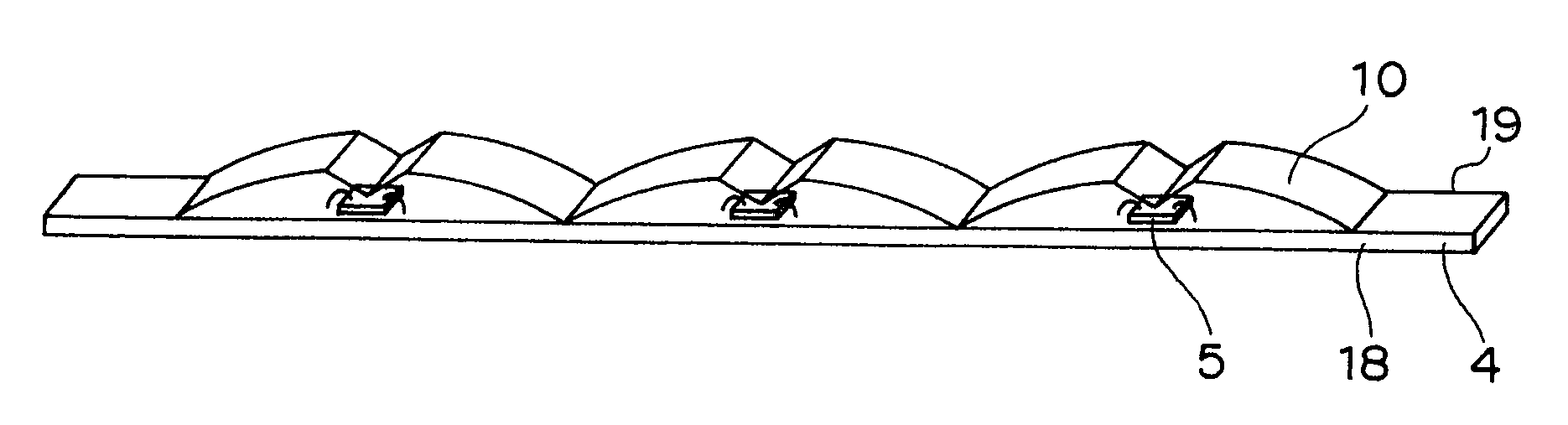
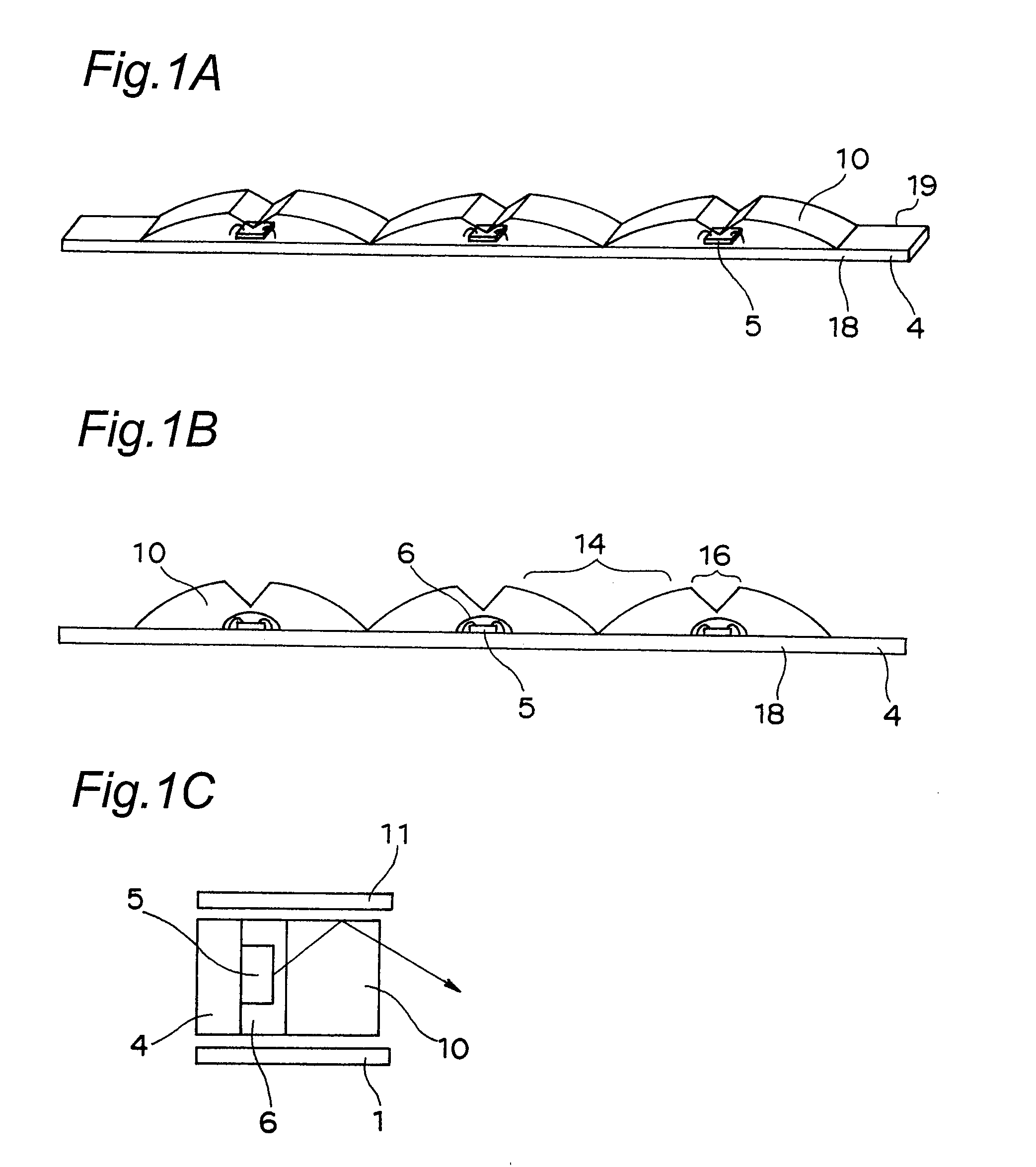
[0162]FIG. 1A is a perspective view of a line light source device in accordance with a first embodiment of the invention, and FIG. 1B is a longitudinal section of the line light source device of the first embodiment. FIG. 1C is a section of a printed board 4, the section taken through a light emission element 5 along a direction of width of the printed board.

[0163]As shown in FIGS. 1A, 1B and 1C, the line light source device is composed of the printed board 4 that is provided as a circuit board and that is shaped like an elongated thin strip, a plurality of light emission elements 5, transparent sealing resin layers 6 having phosphor, as an example of fluorescent substance containing parts, transparent sealing resin layers 10 substantially free of phosphor, a lower reflection sheet 1, and an upper reflection sheet 11, as reflection members.

[0164]As shown in FIG. 1B, the plurality of light emission element 5 are placed in a row on one surface of the printed board 4, at some intervals...

second embodiment

[0213]FIG. 5A is a perspective view of a line light source device in accordance with a second embodiment of the invention, and FIG. 5B is a longitudinal section of the line light source device of the second embodiment. FIG. 5C is a section of a printed board, the section taken through a light emission element 5 having reflection sheets along a direction of width of the printed board.

[0214]Components of the line light source device of the second embodiment that are the same as the components of the line light source device of the first embodiment are designated by the same reference numerals and description thereof is omitted. For the line light source device of the second embodiment, description is omitted on functional effects and modifications that are common to those of the line light source device of the first embodiment but is provided only on configurations, functional effects, and modifications that are different from those of the line light source device of the first embodim...

third embodiment

[0220]FIG. 6A is a perspective view of a line light source device in accordance with a third embodiment of the invention, and FIG. 6B is a longitudinal section of the line light source device of the third embodiment. FIG. 6C is a section of a printed board, the section taken through a light emission element 5 having reflection sheets along a direction of width of the printed board.

[0221]Components of the line light source device of the third embodiment that are the same as the components of the line light source device of the first embodiment are designated by the same reference numerals and description thereof is omitted. For the line light source device of the third embodiment, description is omitted on functional effects and modifications that are common to those of the line light source device of the first embodiment but is provided only on configurations, functional effects, and modifications that are different from those of the line light source device of the first embodiment....


PUM

PropertyMeasurementUnit
refractive indexaaaaaaaaaa
critical angle θcaaaaaaaaaa
heightaaaaaaaaaa

Abstract

In the line light source device and the plane light emission device, first recesses 14 are formed between adjoining light emission elements 5, on surfaces of sealing resin layers 10 opposite to the board 4. The line light source device and the plane light emission device, in which the light emission elements are coated with resin, have a simple configuration and high uniformity in luminous intensity in an emission end face of the device.

Description

CROSS-REFERENCE TO RELATED APPLICATIONS[0001]This nonprovisional application claims priority under 35 U.S.C. §119(a) on Patent Application No(s). 2007-156119 filed in Japan on Jun. 13, 2007 and 2008-142689 filed in Japan on May 30, 2008, the entire contents of which are hereby incorporated by reference.BACKGROUND OF THE INVENTION[0002]The present invention relates to a line light source device, a plane light emission device that are preferably used as a backlight of a liquid crystal display panel, e.g., in a portable telephone, a digital camera, or a portable game machine, and a liquid crystal display.[0003]The invention particularly relates to a line light source device that are preferably used as a backlight of a liquid crystal display panel of a portable telephone having a frame reduced in size and thickness and shaped like a narrow picture frame, a personal digital assistant, a digital camera, a portable game machine or the like, a plane light emission device, and a liquid cryst...

Claims


Application Information

Patent Timeline
Patent Type & Authority Applications(United States)
IPC IPC(8): G02F1/1335F21S4/00F21V9/16F21V21/00F21V7/00F21V9/40H01L33/50H01L33/54H01L33/56H01L33/62
CPCG02B6/0018G02B6/0023G02B6/003G02B6/0068G02F1/133603H01L2224/48091G02F2001/133607H01L2924/00014G02F1/133607
Inventor ITOH, SHINSUMIKAWA, MASATONAKAMURA, YOSHINOBUIKEHARA, MASAHIROINOGUCHI, TSUKASA
Owner SHARP KK
Why Eureka
Try Eureka