Converted Mode Seismic Survey Design
a seismic survey and conversion mode technology, applied in the field of geophysical prospecting, can solve the problems of sp survey being problematic to implement in the marine environment, the method and procedure used in designing common mode reflection seismology surveys are not directly applicable to designing converted mode reflection seismology surveys,
- Summary
- Abstract
- Description
- Claims
- Application Information
AI Technical Summary
Benefits of technology
Problems solved by technology
Method used
Image
Examples
example 1
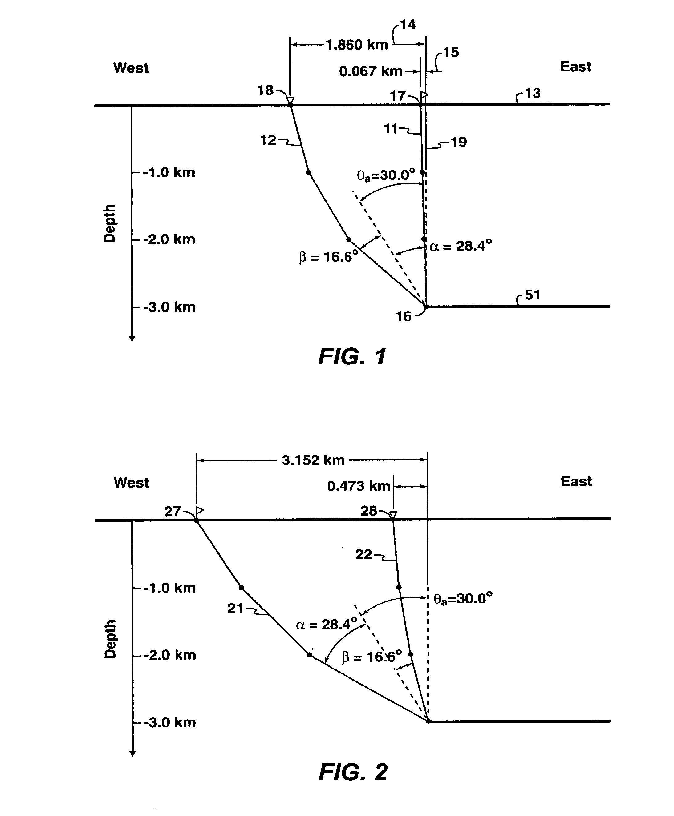
[0079]A PS converted wave seismic survey is desired to image a depth of 3000 meters over a square area that is 4000 meters on each side, the sides of the square aligned along east-west and north-south directions. The survey orientation is such that source and receiver offsets have predominantly east-west and west-east azimuths. The earth is well approximated by a layered compressional velocity model given by a propagation velocity of 1500 meters per second from the surface to a depth of 1000 meters, 2000 meters per second from 1000 to 2000 meters depth, and 2500 meters per second below 2000 meters depth; and a layered shear velocity model given by a propagation velocity of 500 meters per second from the surface to a depth of 1000 meters, 1000 meters per second from 1000 to 2000 meters depth, and 1500 meters per second below 2000 meters depth. No independent information on the energy distribution with scattering angle is available, nor has any range of incident angles been specified ...
example 2
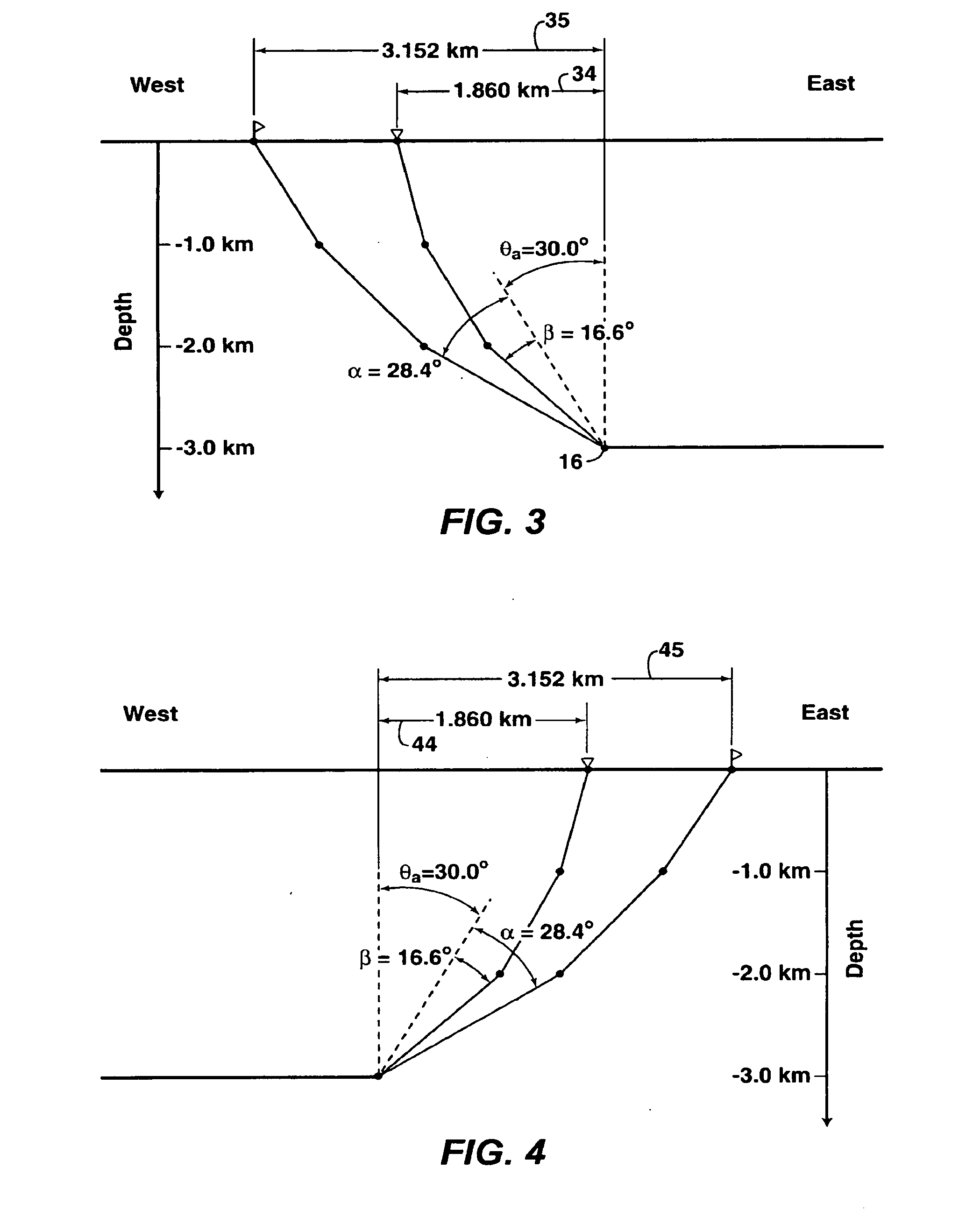
[0102]This example is the same as Example 1, except it has been specified that the maximum offset to be acquired for the survey is 3000 meters, and that this offset contains more converted mode seismic energy than smaller offsets. Since scattering angle is related to offset, the maximum offset sets the maximum scattering angle that will be acquired.
[0103]i) Determine the Bandwidth Required to Achieve the Specified Vertical to Seismic Resolution at the Target Depth.
[0104]In this case, the offset of 3000 meters has been identified as the maximum offset to be acquired by the survey and that this offset contains the most converted mode energy. Therefore, the survey designer has chosen to base the bandwidth requirement on the 3000 meter offset.
[0105]First, the scattering angle that corresponds to an offset of 3000 meters is determined by ray tracing. A 3000 meter offset from specular reflection off a horizontal reflector at the target depth corresponds with a scattering angle of 69.0°. T...
example 3
[0115]This example is the same as Example 2, except it has been specified that only east-west orientations of source—receiver pairs will be acquired for imaging. The solutions to steps i) and iii) are the same as in Example 2 and are not repeated for Example 3. But the aperture solution in step ii) is different than Example 2 because both east-west and west-east orientations of source—receiver pairs were required for imaging in Example 2, but only east-west orientations of source—receiver pairs will be acquired for imaging in Example 3.
[0116]i) Determine the Bandwidth Required to Achieve the Specified Vertical Seismic Resolution at the Target Depth.
[0117](Solution is given in step i) of Example 2)
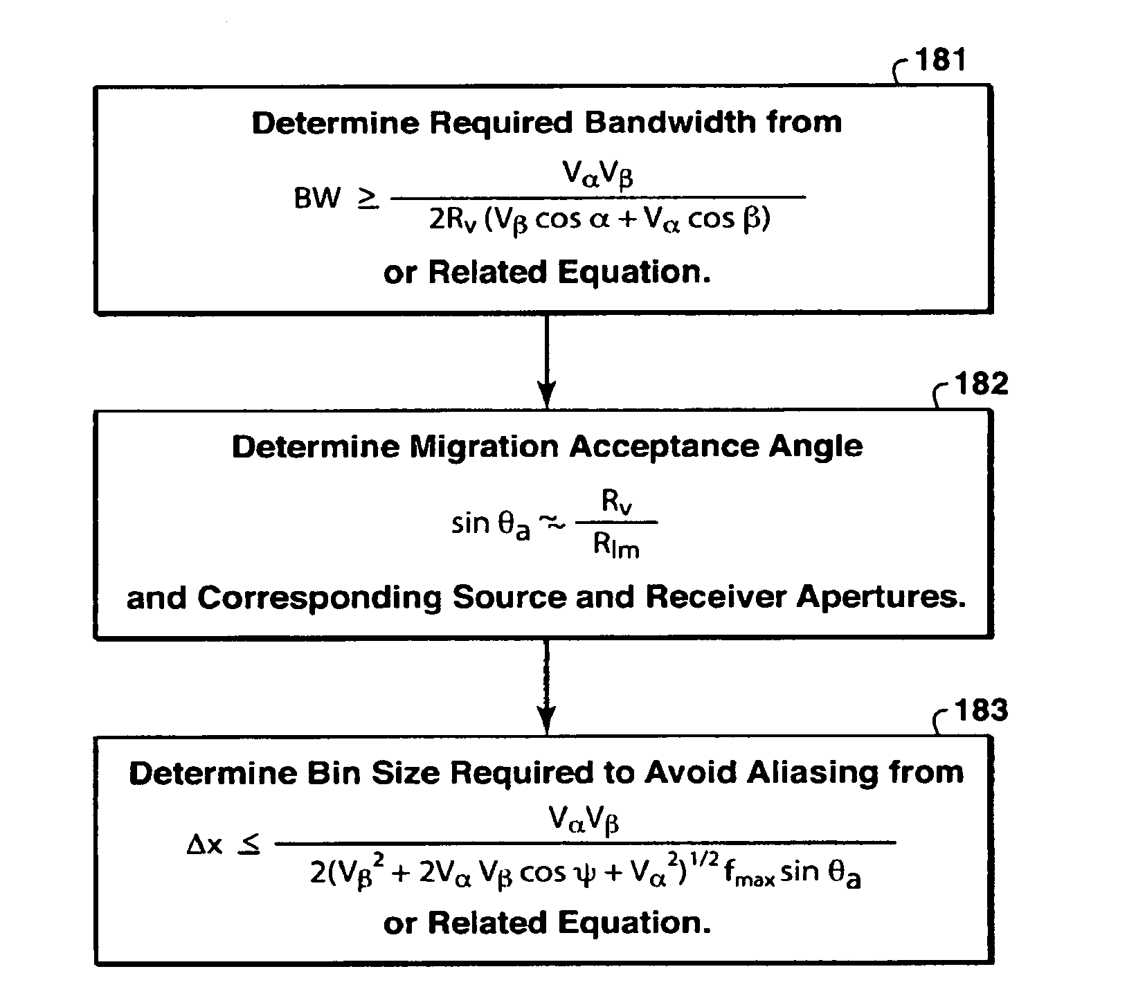
[0118]ii) Determine the Migration Acceptance Angle and Corresponding Source and Receiver Apertures Required to Achieve the Specified Lateral Seismic Resolution at the Target Depth.
[0119]The minimum required migration acceptance angle is determined by
θa≈arcsinRvRlm.
[0120]Evaluating, the requ...
PUM
 Abstract
Description
Claims
Application Information
 - R&D
- Intellectual Property
- Life Sciences
- Materials
- Tech Scout
- Unparalleled Data Quality
- Higher Quality Content
- 60% Fewer Hallucinations
Browse by: Latest US Patents, China's latest patents, Technical Efficacy Thesaurus, Application Domain, Technology Topic, Popular Technical Reports.
© 2025 PatSnap. All rights reserved.Legal|Privacy policy|Modern Slavery Act Transparency Statement|Sitemap|About US| Contact US: help@patsnap.com


