Optical pickup, optical information recording/reproducing apparatus using the same, and phase variable wave plate used in the pickup and the apparatus

a technology of optical information and pickups, applied in combination recording, data recording, instruments, etc., can solve the problems of inability to achieve sufficient reproducing signals, difficulty in numerical aperture na of the objective lens larger than the current value of 0.6, and inability to achieve cd-r. , to achieve compatibility, stable signal detection, and simple configuration

Inactive Publication Date: 2005-02-10
PANASONIC CORP
View PDF7 Cites 9 Cited by
  • Summary
  • Abstract
  • Description
  • Claims
  • Application Information

AI Technical Summary

Benefits of technology

[0018] It is an object of the present invention to solve the above-mentioned problems of the prior art and to provide a small-size optical pickup that, with a simple configuration, achieves compatibility between multiple types of ...

Problems solved by technology

However, although the optical system using the bifocal lens realizes the compatibility with the CD, it cannot yet achieve that with a CD-R.
This is because a sufficient reproducing signal cannot be obtained due to the rather poor reflective properties of the CD-R in the red region.
However, making the numerical aperture NA of the objective lens larger than the current value of 0.6 is difficult both from the viewpoints of margins on systems and of compatibility with the CDs and the DVDs.
However, the reflective properties of the CD-Rs and the DVD-Rs deteriorate in the blue region.
However, since the optical pickup that is configured with the coherent light sources of multiple wavelengths neces...

Method used


Image

  • Optical pickup, optical information recording/reproducing apparatus using the same, and phase variable wave plate used in the pickup and the apparatus
  • Optical pickup, optical information recording/reproducing apparatus using the same, and phase variable wave plate used in the pickup and the apparatus
  • Optical pickup, optical information recording/reproducing apparatus using the same, and phase variable wave plate used in the pickup and the apparatus

Examples


first embodiment

[0068] First Embodiment

[0069] In the present embodiment, an optical pickup that is provided with coherent light sources respectively emitting lights in two wavelength regions of a blue region and a red region and has an optical detection system using a polarizing hologram element and a wave plate is described.

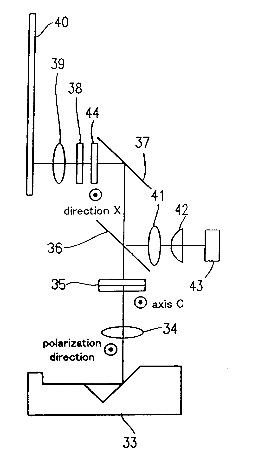
[0070]FIG. 1 shows a schematic diagram of the optical pickup in accordance with a first embodiment of the present invention.

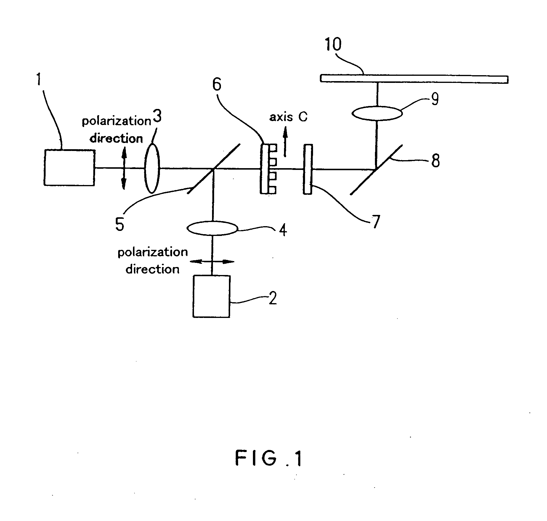
[0071] The present embodiment uses a SHG blue laser unit 1 using a second harmonic generation (SHG) technique as the coherent light source in the blue region. FIG. 2 shows a configuration of the SHG blue laser unit 1. The SHG blue laser unit 1 includes a near infrared semiconductor laser and an optical waveguide wavelength-converting element.

[0072] In the configuration shown in FIG. 2, a distributed Bragg reflecting (DBR) semiconductor laser 11 in which the wavelength can be varied is used as the near infrared semiconductor laser. The DBR semiconductor ...

second embodiment

[0100] Second Embodiment

[0101] In the present embodiment, an optical pickup using a laser unit in which a plurality of coherent light sources emitting lights with different wavelengths are mounted on the same substrate (submount) is described.

[0102] Specifically, in the present embodiment, a laser unit in which a GaN blue semiconductor laser chip (wavelength of 405 nm), an AlGaInP red semiconductor laser chip (wavelength of 650 nm) and an AlGaAs near infrared semiconductor laser chip (wavelength of 790 nm) are mounted on a Si-submount is described. FIG. 4 shows a schematic diagram of the optical pickup in accordance with the present embodiment, and FIG. 5 shows a schematic diagram of a laser unit used therein.

[0103] As is shown in FIG. 5, the GaN blue semiconductor laser chip 45, the AlGaInP red semiconductor laser chip 46 and the AlGaAs near infrared semiconductor laser chip 47 are mounted on the Si-submount 45-4. The blue semiconductor laser chip 45 (wavelength of 405 nm) that p...

third embodiment

[0126] Third Embodiment

[0127] In the present embodiment, an optical pickup in which lights emitted from a plurality of coherent light sources can be coupled by a dielectric multi-layer film mirror as a light coupling member and focused on an optical disk by a single objective lens is described. Generally, light transmitted and reflected by a plurality of optical components is affected by aberration of the optical components. A configuration in accordance with the present embodiment is effective in solving this problem.

[0128]FIG. 9 shows a schematic diagram of the optical pickup in accordance with the present embodiment. As is shown in FIG. 8, the optical pickup of the present embodiment has a GaN blue semiconductor laser unit 57 (wavelength of 405 nm), an AlGaInP red semiconductor laser unit 58 (wavelength of 650 nm) and an AlGaAs near infrared semiconductor laser unit 59 (wavelength of 790 nm) in which photo detectors are integrated respectively. Lights emitted from these laser un...


PUM


Abstract

Laser beams respectively emitted from a SHG blue laser unit and a red semiconductor laser unit that have photo detectors respectively are turned into parallel lights by a collimator lens and then coupled by a dielectric multi-layer film mirror so as to be propagated on the same optical axis. The dielectric multi-layer film mirror is configured so as to transmit light with a wavelength of 500 nm or shorter and reflect light with a wavelength of 500 nm or longer for both P wave and S wave. The lights that are transmitted and reflected by the dielectric multi-layer film mirror pass through a polarizing hologram and a phase variable wave plate and are focused on an optical disk by an objective lens. In this manner, a simple configuration can realize a compatibility with many types of optical disks and a stable signal detection even when using a polarizing optical detection system.

Description

FIELD OF THE INVENTION [0001] The present invention relates to an optical pickup that is provided with a plurality of light sources emitting light beams with different wavelengths (for example, semiconductor lasers), an optical information recording / reproducing apparatus using the same, and a phase variable wave plate used in the pickup and the apparatus. BACKGROUND OF THE INVENTION [0002] In 1996, a DVD (digital versatile disk) system having a recording capacity of 4.7 GB was developed by using an AlGaInP red semiconductor laser (a wavelength of approximately 650 nm). A conventional. CD (compact disk) system had used an AlGaAs near infrared semiconductor laser (a wavelength of approximately 780 nm) and had a recording capacity of 650 MB. [0003] There are many points differentiating the DVD system from the CD system. One of them is the base material thickness of an optical disk used. Specifically, the base material thickness of the optical disk is 1.2 mm in the CD system, while it i...

Claims


Application Information

Patent Timeline
IPC IPC(8): G11B7/00G11B7/125G11B7/135G11B11/00
CPCG11B7/1275G11B7/1362G11B2007/0006G11B7/1369G11B7/13925G11B7/1367
Inventor KITAOKA, YASUOKASAZUMI, KEN'ICHIKUMAGAWA, KATSUHIKOYAMAMOTO, KAZUHISAWADA, HIDENORI
Owner PANASONIC CORP
Why Eureka
Try Eureka