

Data switching method and circuit
- Summary
- Abstract
- Description
- Claims
- Application Information
AI Technical Summary
Benefits of technology
Problems solved by technology
Method used
Image

Examples
embodiment
[2]
FIGS. 4 and 5
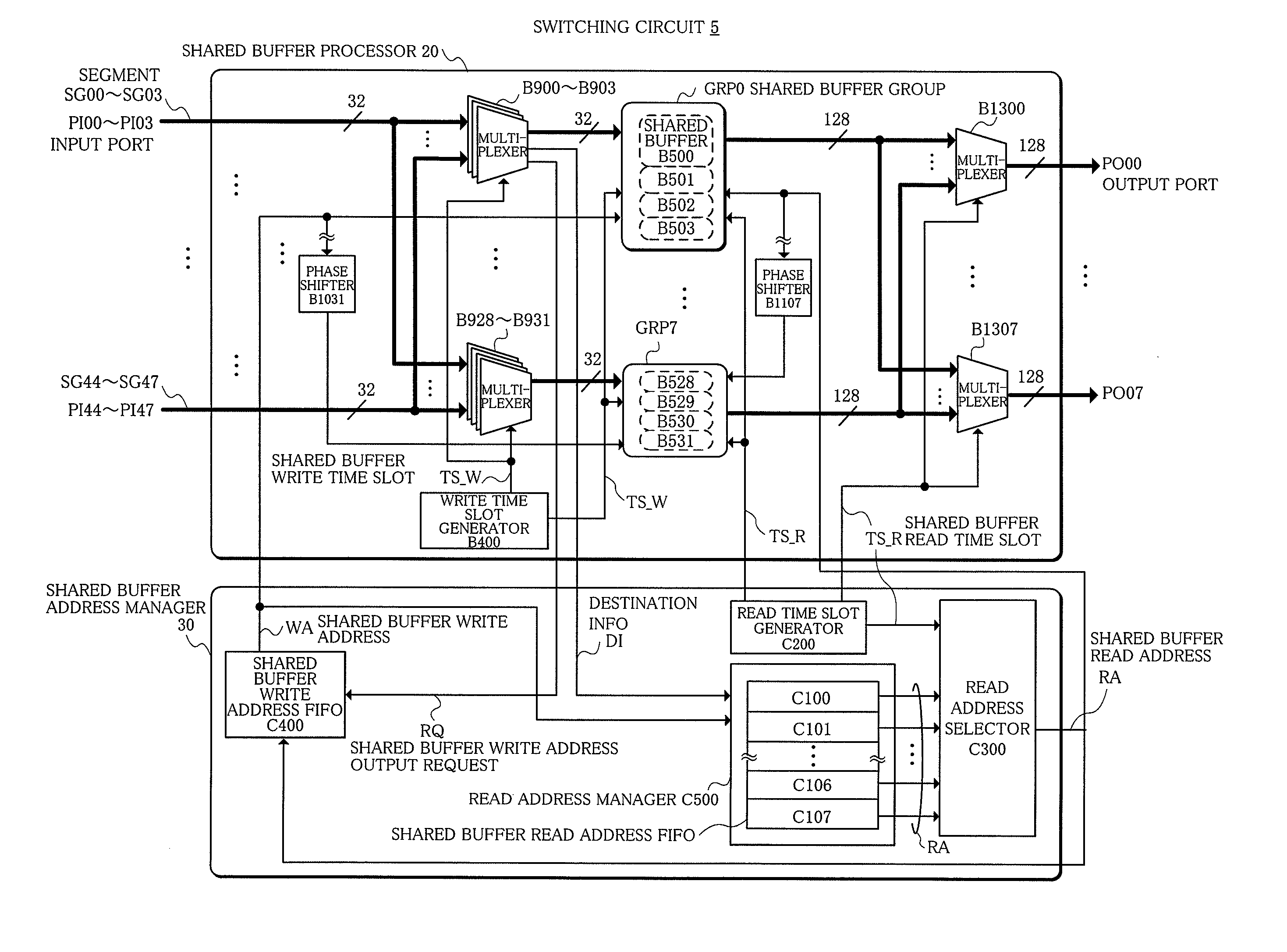
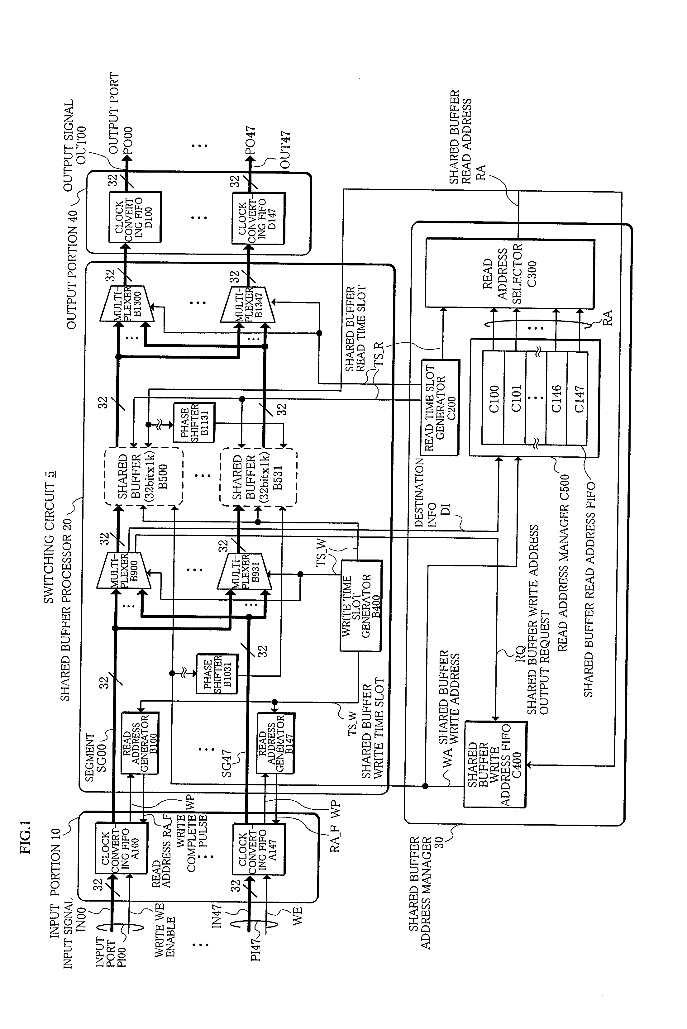
[0061]A switching circuit 5 according to an embodiment [2] shown in FIG. 4 is different from the one in the above embodiment [1] in that there are provided eight output ports PO00-PO07 each having a data width of 128 bits, in accordance with which the shared buffers B500-B531 are divided into eight groups GRP0-GRP7 each having four shared buffers (32 bits×4).
[0062]Also, the shared buffer processor 20 comprises phase shifters B1101-B1107 for shifting the phases of the shared buffer read addresses RA in sequence between the groups GRP0-GRP7, and multiplexers B1300-B1307 provided corresponding to the groups GRP0-GRP7.
[0063]Furthermore, the number of read address FIFOs managed by the read address manager C500 inside the shared buffer address manager 30 is modified to 8 (C100-C107) corresponding to the number (8) of the output ports.
[0064]It is to be noted that for the simplification of the figures, the depiction of the input portion 10, read address generators B100-B147 ...
PUM
 Abstract
Description
Claims
Application Information