Switching power supply apparatus

a technology of switching power supply and power supply apparatus, which is applied in the direction of electric variable regulation, process and machine control, instruments, etc., can solve the problems of large circuit scale, difficult to detect overload state with high accuracy, and increase the cost of switching power supply apparatus, etc., and achieves low cost and high accuracy.

Active Publication Date: 2019-01-29
FUJI ELECTRIC CO LTD
View PDF15 Cites 0 Cited by
  • Summary
  • Abstract
  • Description
  • Claims
  • Application Information

AI Technical Summary

Benefits of technology

[0008]The present invention has been accomplished in consideration of such circumstances. An object of the invention is to provide a switching power supply apparatus provided with an overload detecting circuit which has a simple configuration and which can detect an overload with high accuracy without incurring an increase in the scale of the circuit configuration.
[0017]According to the switching power supply apparatus configured as described above, paying attention to the fact that a resonance current in the inductor is constituted by a load current and an excitation current, the load state of the power converting device body is detected based on a peak value or an effective value of a resonance voltage generated due to resonance of the inductor. Thus, the load state can be detected simply and with high accuracy. In addition, the load state can be detected simply without requiring any complicated calculation processing on the primary winding side of the isolation transformer as in the background art. Accordingly, it is possible to obtain effects including an effect that the switching power supply apparatus provided with the overload detecting circuit can be constructed inexpensively.

Problems solved by technology

However, the switching power supply apparatus provided with the overload detecting circuit on the secondary side of the isolation transformer has a large-scale configuration.
In addition, it cannot be denied that the configuration causes increase in the cost of the switching power supply apparatus.
Moreover, when the detection accuracy of the VS voltage and the resonance current and the calculation accuracy in an integrating circuit are taken into consideration, it is difficult to detect an overload state with high accuracy.
In addition, in the technique disclosed in JP-A-2012-170218, there is a problem that the circuit scale becomes large because an averaging circuit, a multiplying circuit, etc. are necessary for averaging the resonance current.

Method used


Image

  • Switching power supply apparatus
  • Switching power supply apparatus
  • Switching power supply apparatus

Examples


Embodiment Construction

[0029]Current resonance type switching power supply apparatus according to embodiments of the invention will be described below with reference to the drawings.

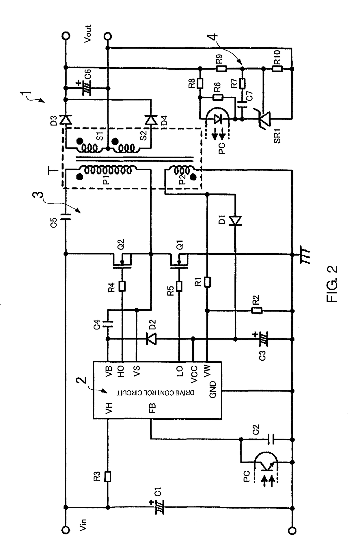
[0030]FIG. 2 is a schematic configuration view of a current resonance type switching power supply apparatus (DC-DC converter) according to a first embodiment of the invention. This switching power supply apparatus 1 is mainly constituted by a series resonant circuit, which is formed by leakage inductance (leakage inductance) of an isolation transformer T, and a capacitor C5 through which a primary winding P1 of the isolation transformer T is connected to a DC input voltage source. A first switching element Q1 connected in series with the primary winding P1 of the isolation transformer T is driven to turn ON by a drive control circuit (power supply IC) 2 performing a separately-excited oscillation operation, so as to apply an input voltage Vin from the DC input voltage source to the series resonant circuit. In addition, a secon...


PUM


Abstract

A switching power supply apparatus, including a power converting device body configured to switch DC input power through a first switching element to thereby store the DC input power in an inductor, and to transfer the stored power to an output capacitor through a second switching element by use of resonance of the inductor, a control circuit configured to drive the first and second switching elements to alternately turn ON or OFF the two switching elements, to thereby resonate the inductor, and an overload detecting circuit configured to detect a load state of the power converting device body based on a peak value or an effective value of a resonance voltage generated from the resonance of the inductor, to thereby control operation of the control circuit.

Description

BACKGROUND OF THE INVENTION[0001]1. Field of the Invention[0002]The present invention relates to a switching power supply apparatus provided with an overload detecting circuit which is high in detection accuracy and simple in configuration.[0003]2. Description of the Background Art[0004]Current resonance type switching power supply apparatus represented by resonance type DC-DC converters or synchronous rectification boost type converters have been used as power supply apparatuses in various kinds of electronic equipment because they are highly efficient and suitable to be thinned. This kind of switching power supply apparatus is typically provided with a protective function by which an overload state of the switching power supply apparatus is detected and ON-driving of switching elements such as IGBTs (insulated-gate bipolar transistors) or MOS-FETs (metal-oxide-semiconductor field-effect transistor) are stopped, so that a load, the switching elements, etc. can be protected.[0005]In...

Claims


Application Information

Patent Timeline
Patent Type & Authority Patents(United States)
IPC IPC(8): H02M1/32H02M3/335H02M3/337H02M1/00
CPCH02M1/32H02M3/3376H02M3/33523H02M2001/0019H02M2001/0058Y02B70/1416Y02B70/1433Y02B70/1491H02M1/0058Y02B70/10H02M1/0019
Inventor CHEN, JIAN
Owner FUJI ELECTRIC CO LTD
Why Eureka
Try Eureka