Image forming apparatus and control method therefor

a technology of image forming apparatus and control method, which is applied in the direction of electrographic process apparatus, instruments, optics, etc., can solve the problems of image quality, degrade or even damage the heat generator, and the electromechanical induction-heating fixing method still has a problem described, so as to reduce the temperature difference

Active Publication Date: 2009-12-03
RICOH KK
View PDF4 Cites 105 Cited by
  • Summary
  • Abstract
  • Description
  • Claims
  • Application Information

AI Technical Summary

Benefits of technology

[0019]In another illustrative embodiment of the present embodiment provides a control method for the image forming apparatus described above. The control method includes completing a first image formation job, detecting a temperature of a center portion and an end portion of the rotary heat generator, and, based on the detected temperature, controlling activation of the excitation coil as well as the demagnetization coil before start of a second image formation job following the first image formation job in which an image is formed on a sheet of recording media whose width is smaller than a maximum sheet width usable in the fixer so as to reduce a difference in temperature between the center portion and the end portion of the rotary heat generator.

Problems solved by technology

However, the electromagnetic induction-heating fixing method still has a problem described below in detail.
Such overheating can degrade or even damage the heat generator.
This peripheral overheating and its resultant uneven temperature distribution have consequences for image quality.
Hot offset occurs because, when toner is heated excessively, cohesion among toner particles is lower than adhesion between the toner particles and the fixing member, thereby, causing toner layers to separate.
In another known method, activation of the demagnetization coils is adjusted according to sheet size because heating might be insufficient if the demagnetization coils are constantly on.
However, in these methods, when small sheets are continuously passed through the fixing nip, even when the demagnetization coils restrict the excessive temperature rise of the heating generator, the temperature of the non-sheet area is higher than that of the sheet area.
Therefore, when a relatively large sheet is passed through the fixing nip immediately after small sheets are continuously passed through the fixing nip, the gloss level can be uneven between the center portion and the lateral end portions of the sheet.

Method used


Image

  • Image forming apparatus and control method therefor
  • Image forming apparatus and control method therefor
  • Image forming apparatus and control method therefor

Examples


Embodiment Construction

[0042]In describing preferred embodiments illustrated in the drawings, specific terminology is employed for the sake of clarity. However, the disclosure of this patent specification is not intended to be limited to the specific terminology so selected, and it is to be understood that each specific element includes all technical equivalents that operate in a similar manner and achieve a similar result.

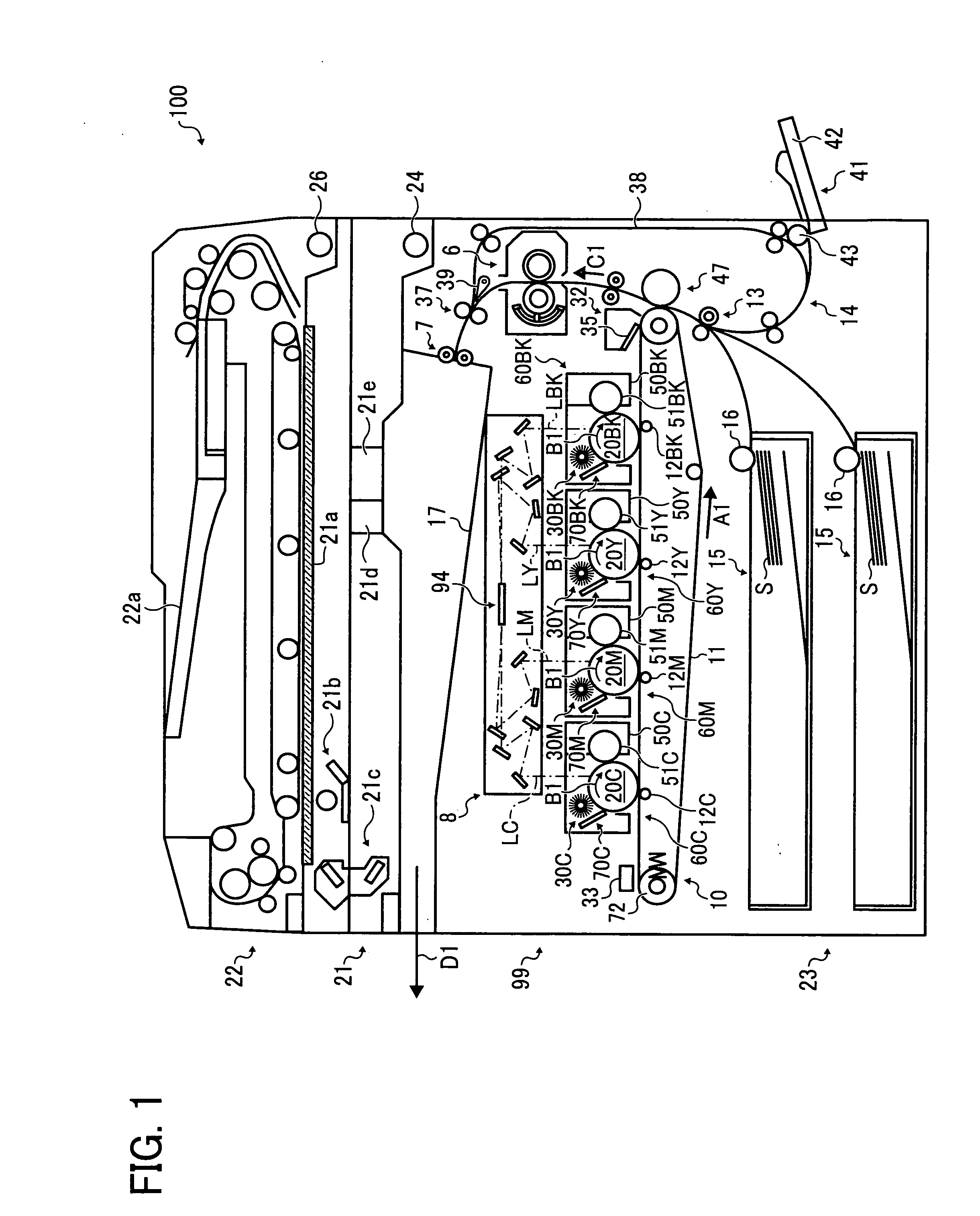
[0043]Referring now to the drawings, wherein like reference numerals designate identical or corresponding parts throughout the several views thereof, and particularly to FIG. 1, an image forming apparatus according to an illustrative embodiment of the present invention is described.

[0044]FIG. 1 is a schematic diagram illustrating a configuration of an image forming apparatus 100, and the right and the left in FIG. 1 are respectively a front side and a back side of the image forming apparatus 100.

[0045]In the present embodiment, the image forming apparatus 100 is a multifunction machine ...


PUM


Abstract

An image forming apparatus includes an image carrier, a developing unit, a transfer unit, and a fixer to fix an image formed on a sheet and includes a rotary heat generator including a heat generation layer, a pressure member to form a nip with the rotary heat generator to sandwich the sheet therebetween, an excitation coil disposed facing the rotary heat generator, to inductively heat the heat generation layer, a demagnetization coil disposed facing the heat generation layer, to generate magnetic flux that partly counteracts magnetic flux generated by the excitation coil and a fixer controller to control activation of the excitation coil as well as the demagnetization coil before a second image formation job after completion of a first image formation job in which an image is formed on a sheet of recording media whose width is smaller than a maximum sheet width usable in the fixer.

Description

CROSS-REFERENCE TO RELATED APPLICATIONS[0001]This patent specification claims priority from Japanese Patent Application No. 2008-143879, filed on May 30, 2008 in the Japan Patent Office, the entire contents of which are hereby incorporated by reference herein.BACKGROUND OF THE INVENTION[0002]1. Field of the Invention[0003]The present invention generally relates to an image forming apparatus, such as a copier, a printer, a facsimile machine, or a multifunction machine, that includes a fixer, and a fixing method, and more particularly, to an electromagnetic induction heating fixer, an image forming apparatus including the same, and a fixing method using the same.[0004]2. Discussion of the Background Art[0005]In general, an electrophotographic image forming apparatus, such as a copier, a printer, a facsimile machine, and a multifunction machine including at least two of those functions, forms an electrostatic latent image on an image carrier, develops the latent image with developer su...

Claims


Application Information

Patent Timeline
Patent Type & Authority Applications(United States)
IPC IPC(8): G03G15/20
CPCG03G15/2042
Inventor HASE, TAKAMASA
Owner RICOH KK
Why Eureka
Try Eureka