RF antenna assembly for treatment of inner surfaces of tubes with inductively coupled plasma

Inactive Publication Date: 2009-12-03
GLUKHOY YURI +2
View PDF11 Cites 39 Cited by
  • Summary
  • Abstract
  • Description
  • Claims
  • Application Information

AI Technical Summary

Benefits of technology

[0023]It is an object of the present invention to provide an antenna assembly with an RF antenna that generates a transverse magnetic field perpendicular to the longitudinal axis of the antenna for generation of inductively coupled plasma inside a plastic tube for forming a thin coating film impermeable to fluids and having high wear-resistant and corrosion-resistant properties. It is another object to provide an antenna assembly of the aforementioned type, which is suitable for use in a PECVD process. It is a further object to provide the aforementioned antenna assembly wherein the antenna is provided with a rotating magnetic field. It is a further object to provide the a

Problems solved by technology

However, all these methods relate to application of anti-corrosive and wear-resistant coatings onto inner surfaces of metal tubes and are not applicable for tubes made from plastic material, in particular, to those plastic tubes which are used in pharmaceutical or food industry.
However, the scope of application of the method of the aforementioned invention is limited and is applicable only to those tubes which are made from materials permeable to microwave energy.
However, HDPE has one drawback, and this is permeation of fuels.
However, a flat substrate such as a semiconductor wafer, which is an object of deposition, can be treated at high temperatures with application of a bias voltage, while in the case of plastic containers or tubes, the material of such containers has a low melting point that cannot withstand high temperatures.
Because of the flammability and explosiveness of silanes, the above process requires special, expensive facilities in the semiconductor industry.
The pure SiO2 barrier, however, presents some disadvantages because it is brittle and can be torn during bending and squeezing.
However, use of axially symmetric antennas is not applicable to elongated containers, e.g., bottles, since they cannot generate plasma having high and uniform density near the inner walls of containers.
Such a system

Method used


Image

  • RF antenna assembly for treatment of inner surfaces of tubes with inductively coupled plasma
  • RF antenna assembly for treatment of inner surfaces of tubes with inductively coupled plasma
  • RF antenna assembly for treatment of inner surfaces of tubes with inductively coupled plasma

Examples


Embodiment Construction

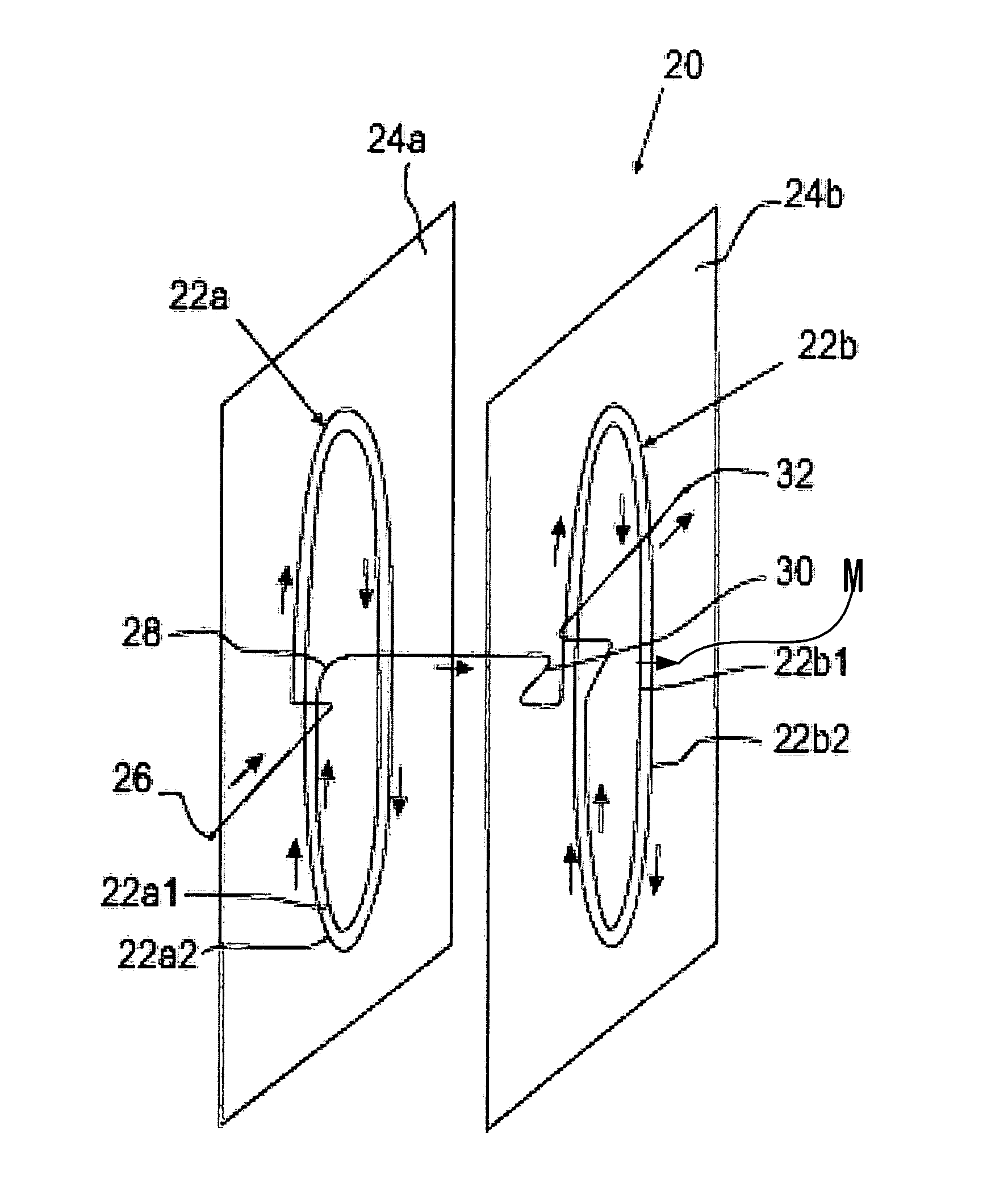
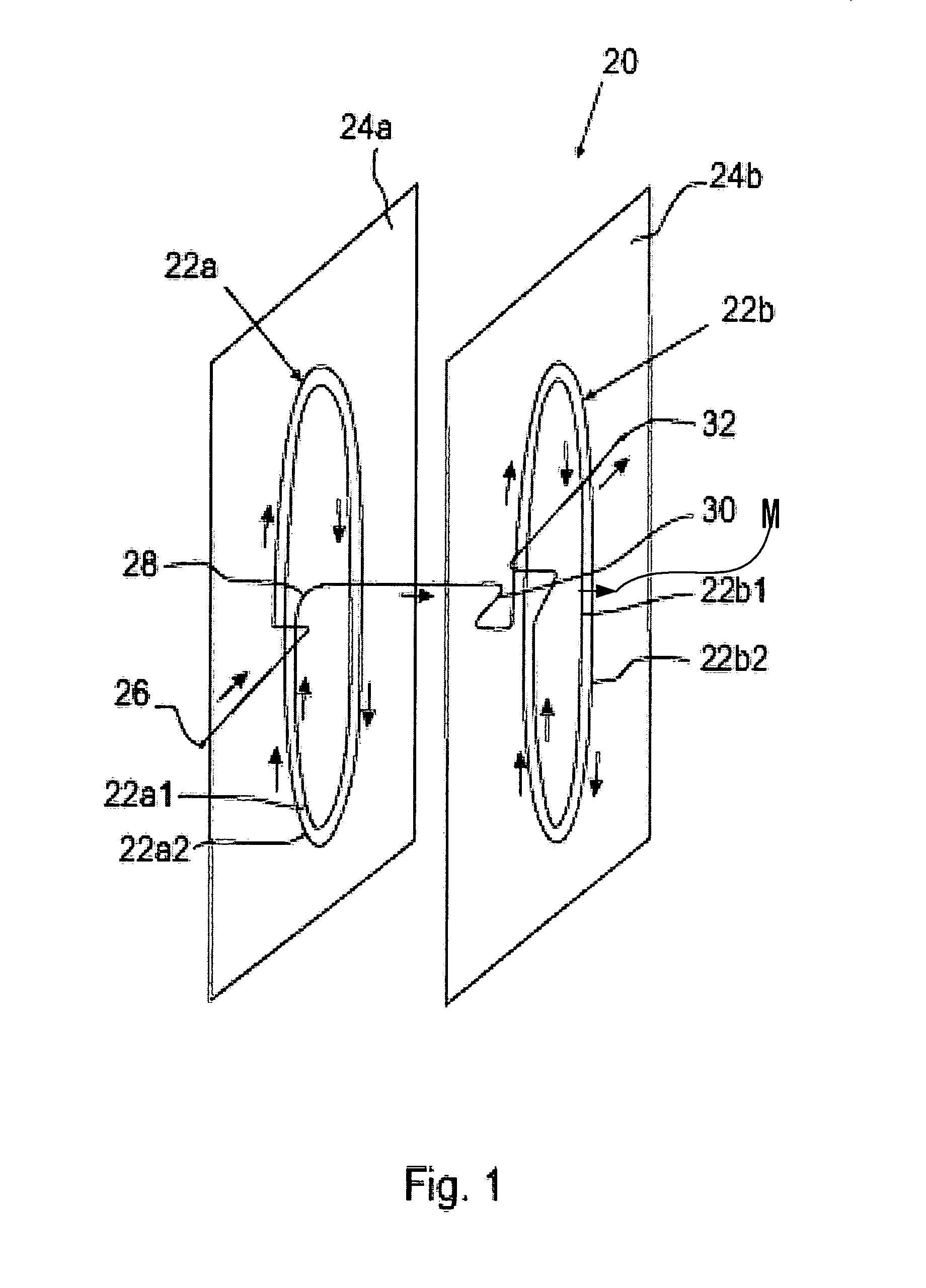
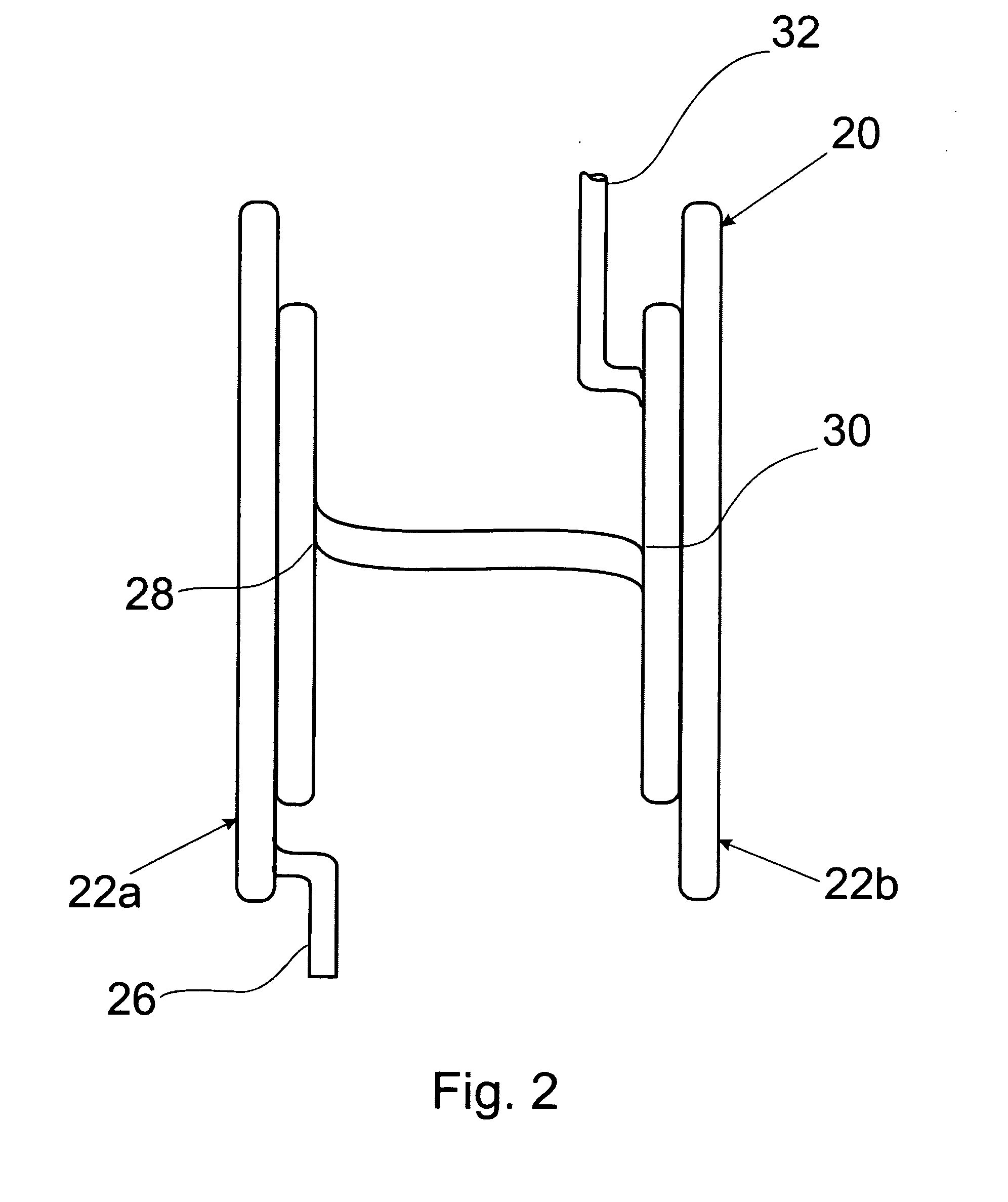
[0041]An example of an antenna assembly of the invention for application of a protective coating onto the inner surface of a tube by means of a PECVD process will now be described with reference to the accompanying drawings.

[0042]Since the transversal RF antenna is the heart of the invention, let us first consider this antenna in more detail.

[0043]The inventor herein has found that in contradiction with the generally accepted erroneous viewpoint that the magnetic field of a solenoid has maximum strength on the longitudinal axis thereof, in reality the strength of the magnetic field on the longitudinal axis of the solenoid is minimal, while the main part of the lines of the magnetic flux is concentrated near the inner area solenoid winding. In order to check this statement it is sufficient to consider a magnetic field of a circular turn through which a current flows and then to summarize (integrate) the result over the solenoid length. Contrary to this, an electric field generated in...


PUM

PropertyMeasurementUnit
Angleaaaaaaaaaa
Flow rateaaaaaaaaaa
Magnetic fieldaaaaaaaaaa

Abstract

An antenna assembly for forming a barrier coating on the inner surface of a tube by means of a sealed annular chemical-plasma-reaction chamber defined by the inner wall of the tube, two spaced elements slidingly and sealingly moveable inside the tube, and a quartz tube that interconnects the cylindrical elements. The coating is formed by a PE CVD process generated inside the chamber by a transversal RF antenna unit which creates a plasma column that participates in rotation simultaneously with linear motion thus providing uniform coating of the inner surface of the tube. The method of the invention consists of depositing a layer of silicon dioxide onto the inner surface of a plastic tube by means of the aforementioned antenna assembly. The plasma column is rotated by the RF magnetic field which is rotated by using two RF generators of different frequencies that energize two groups of specifically interconnected coils.

Description

FIELD OF THE INVENTION[0001]The present invention relates generally to plasma processing and in particular to an RF antenna assembly having an antenna that generates a transversal magnetic field. More specifically, the invention relates to an antenna assembly having an RF antenna with a transversal magnetic field for application of a fluid-impermeable barrier layer onto inner surfaces of non-metal tubes intended for transporting aggressive gaseous or liquid media. The barrier layer is deposited in the form of a thin film by plasma-enhanced chemical vapor deposition (PECVD). In particular, the invention may find use for application of silicon-dioxide coatings onto inner surfaces of plastic tubes used, e.g., in food industry.BACKGROUND OF THE INVENTION AND DESCRIPTION OF THE PRIOR ART[0002]Methods and devices for coating inner surfaces of tubes are known in the art. For example, coating technology used for tubes employed in oil and gas industry includes methods such as chemical vapor ...

Claims


Application Information

Patent Timeline
IPC IPC(8): C23C16/505
CPCC23C16/045H01J37/321C23C16/509C23C16/402
Inventor GLUKHOY, YURIKERZHNER, TATIANARYABOY, ANNA
Owner GLUKHOY YURI
Why Eureka
Try Eureka