Knee brace for rehabilitation

a knee brace and joint brace technology, applied in the field of knee braces, can solve the problems of limiting the moving angle between the upper and lower braces, affecting the effect of the joint brace, so as to reduce the counterforce

Inactive Publication Date: 2009-12-03
PLUS MEDITECH
View PDF3 Cites 25 Cited by
  • Summary
  • Abstract
  • Description
  • Claims
  • Application Information

AI Technical Summary

Benefits of technology

[0010]One difference between the disclosed knee brace for rehabilitation and the prior art is that the invention uses a positioning pin to fix the relative positions between the limiting blocks on the upper and lower braces and the fixing base. By controlling the motion range of the crank between the upper and lower braces, the moving angles of the upper and lower braces are limited to a certain range. Using such measures, the invention can solve the failure problem of the knee brace for rehabilitation due to a loose pin in the prior art. The reduction of the counterforce forced to the knee joint from the knee brace for rehabilitation can prevent the user's knee joint from further injuries.

Problems solved by technology

Therefore, when the joint is hit with an external force, it can be seriously damaged.
It has a much larger probability to be damaged or age than other joints.
Usually, a pin is directly inserted on the motion track of the crank to restrict its motion range, thereby limiting the moving angle between the upper and lower braces.
However, the pin is too small for holding.
It is thus very inconvenient to adjust the motion angle between the upper and lower braces.
Moreover, the pin is likely to get lost.
Currently, the pin is simply inserted on the motion track of the crank, and there is no mechanism for fixing the pin.
As a consequence, the user's knee joint may be hurt again because the moving angle of the knee is too large.

Method used


Image

  • Knee brace for rehabilitation
  • Knee brace for rehabilitation
  • Knee brace for rehabilitation

Examples


first embodiment

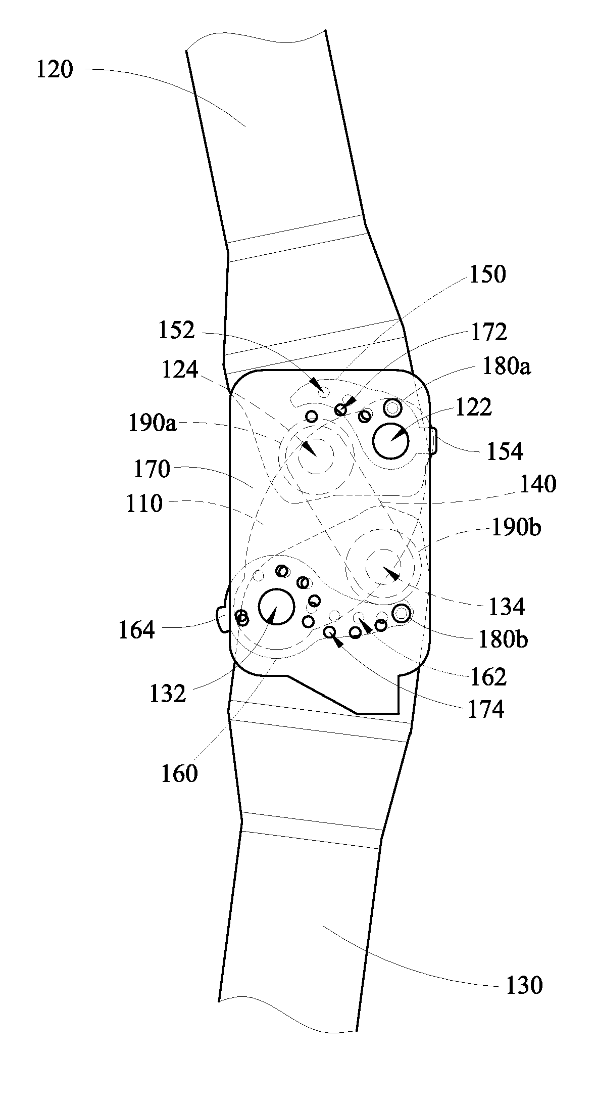
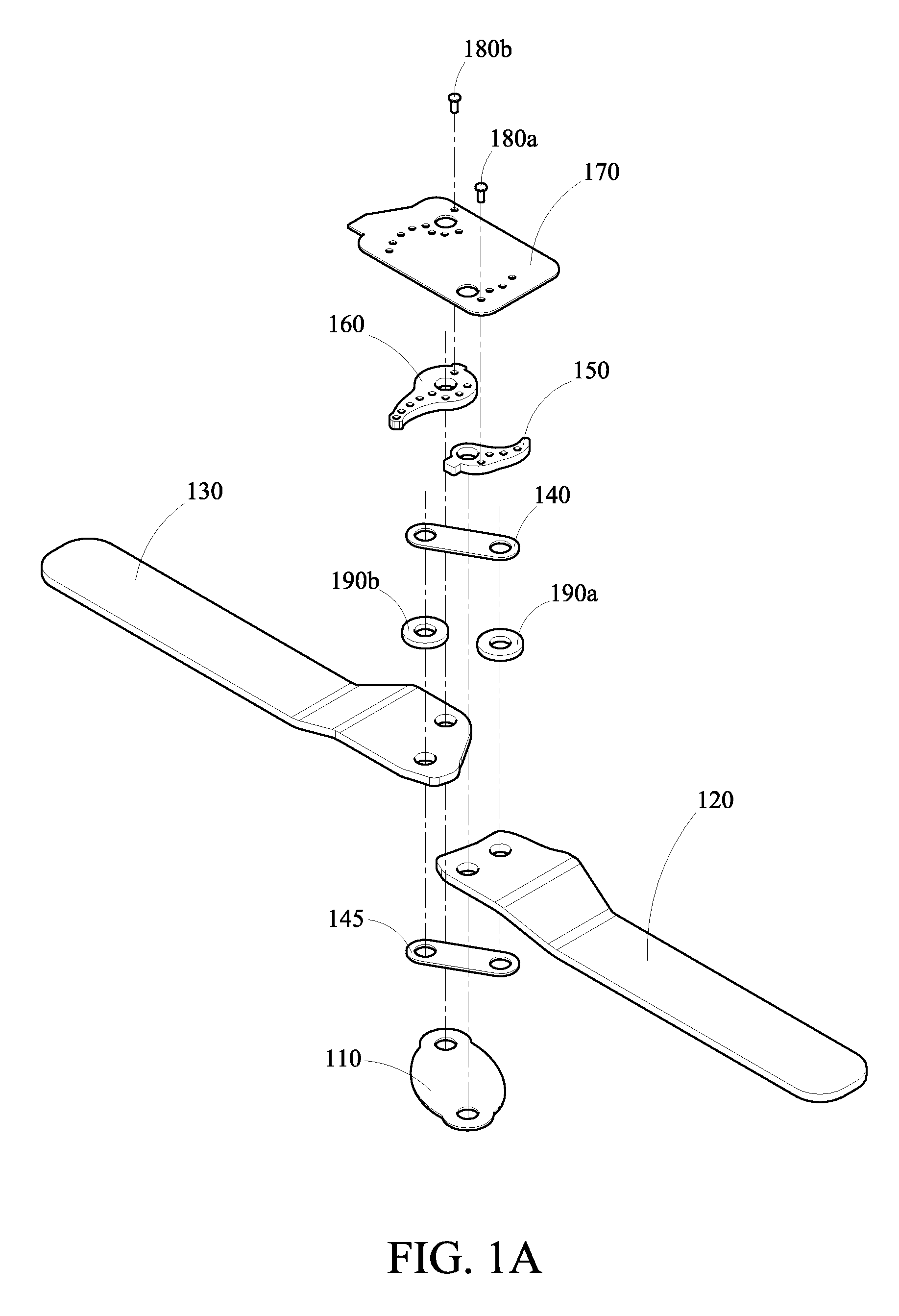
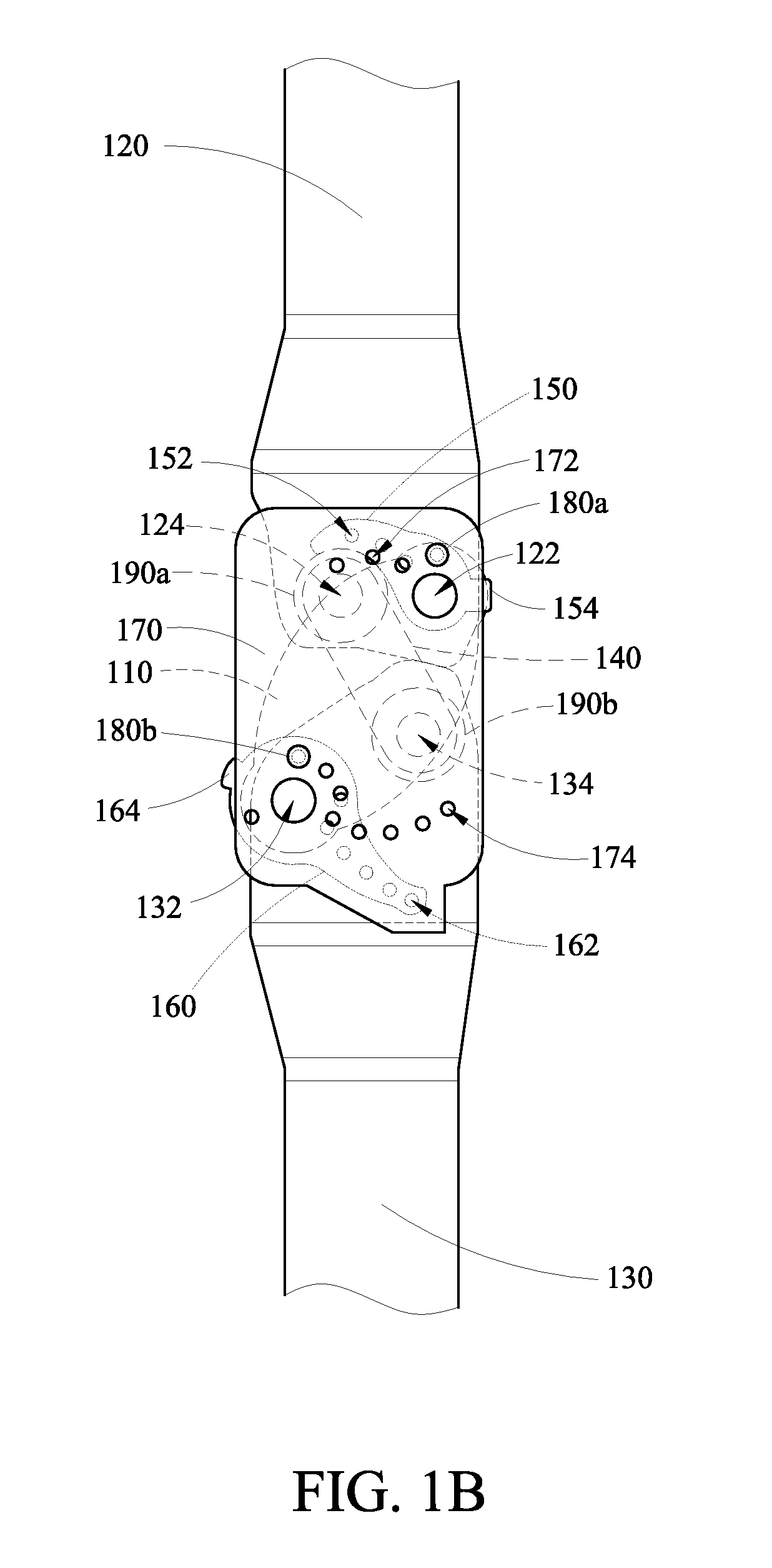
[0035]FIG. 3 is a schematic view of the disclosed knee brace for rehabilitation where the limiting value of extension angle is set to be 150 degrees. As shown in the drawing, if the paramedic evaluates the injured knee joint (anterior cruciate ligament, so-called “ACL”, injury, posterior cruciate ligament, so-called “PCL” injury, or osteoarthritis, so-called “OA”) of the patient and determines that the joint can extend by 150 degrees at most, he or she can use the first adjusting part 150 of the first limiting block 150 to rotate the first limiting block 150 with respect to the first pivotal axis 122 so that the first positioning hole 152 corresponding to the 150-degree limiting extension angle corresponds to the first through hole 172 on the front sheltering plate 170. The positioning pin 180a then goes through the first through hole 172 and gets fixed in the first positioning hole 152. In this case, the first limiting block 150 and the fixing base 110 are fixed as shown in the dra...

second embodiment

[0036]FIG. 4 is a schematic view of the disclosed knee brace for rehabilitation where the limiting value of extension angle is set to be 120 degrees. As shown in the drawing, if the paramedic evaluates the injured knee joint of the patient and determines that the joint can extend by 120 degrees at most, he or she can use the first adjusting part 154 of the second limiting block 160 to rotate the second limiting block 160 with respect to the third pivotal axis 132 so that the second positioning hole 162 corresponding to the 120-degree limiting flexion angle corresponds to the second through hole 174 on the front sheltering plate 170. The positioning pin 180b then goes through the second through hole 174 and gets fixed in the second positioning hole 162. In this case, the second limiting block 160 and the fixing base 110 are fixed as shown in the drawing. As the lower brace 130 swings with the user's leg, the angle between it and the upper brace 120 is at least 120 degrees. That is, t...


PUM


Abstract

A knee brace for rehabilitation provides a stable support for an injured knee using a four-crank mechanism. Positioning pins are used to fix limiting blocks pivoted to the upper and lower braces. It limits the moving range of the crank between the upper and lower braces, restricting the moving angles of the upper and lower braces. Besides, the buffer pads are covered at the pivotal axes of the upper and lower braces in order to alleviate the collision between joint surfaces during the motion of injured knee. Such a mechanism protects the rehabilitating knee joint. The disclosed structure can solve the failure problem of the knee brace for rehabilitation due to a loose pin in the prior art. The counterforce to injured knee from the performance of knee brace reduced for rehabilitation can prevent the user's knee joint from further injuries.

Description

BACKGROUND OF THE INVENTION[0001]1. Field of Invention[0002]The invention relates to a joint brace for rehabilitation and, in particular, to a knee brace for rehabilitation that uses positioning pins to fix limiting blocks, thereby controlling the motion ranges of upper and lower braces connected by a crank.[0003]2. Related Art[0004]Joints connect bones in different portions of the human body. Unlike the middle sections of other bones, the joints do not have the protection of muscles and fats. Therefore, when the joint is hit with an external force, it can be seriously damaged. In particular, the knee joints carry the most burdens. It has a much larger probability to be damaged or age than other joints.[0005]When the knee joint is just hurt, the patient has to reduce or avoid activities. Only after the bone recovers can the patient gradually increase the moving angle of the knee joint. Therefore, rehabilitation tools are often required as an aide. Such a knee brace usually involves ...

Claims


Application Information

Patent Timeline
Patent Type & Authority Applications(United States)
IPC IPC(8): A61F5/00
CPCA61F5/0123A61F2005/0167A61F2005/0148A61F2005/0137
Inventor CHIANG, PANG-CHINGLEE, CHIEN-HUEI
Owner PLUS MEDITECH
Why Eureka
Try Eureka