
Disabling portions of memory with defects

a technology of memory and defects, applied in the direction of memory adressing/allocation/relocation, redundant hardware error correction, instruments, etc., can solve the problems of hard errors that consistently fail, latent defects refer to defects that were not present, and memory errors from the memory point of view

Inactive Publication Date: 2009-12-03
INTEL CORP
View PDF22 Cites 35 Cited by
  • Summary
  • Abstract
  • Description
  • Claims
  • Application Information

AI Technical Summary

Benefits of technology

This approach effectively maintains system uptime and performance by preventing access to defective memory portions, reducing the likelihood of double-bit errors and minimizing the impact of latent defects, while avoiding unnecessary correction efforts.

Problems solved by technology

Such defect may occur and be detected during manufacturing (or “fabricating”) the memory, or such defect may be a latent defect that is not observed until after the memory chip has been supplied by the manufacturer.
Latent defects may be caused, for example, by aging, stresses, and / or actual use of the memory, which results in errors from the point of view of the memory.
Thus, latent defects refer to defects that were not present (or did not manifest themselves) during the testing and production of the memory.
Some latent defects manifest themselves as hard errors which consistently fail when tested for.
Other latent defects manifest themselves as erratic errors which fail inconsistently.
Latent defects in memory if not detected, corrected, or avoided, will cause a running program accessing that portion of memory to crash.
Especially in systems expected to have high uptimes (high availability systems), this is not acceptable.
In addition, it is not acceptable to severely limit the performance of such systems.

Method used


Image

  • Disabling portions of memory with defects
  • Disabling portions of memory with defects
  • Disabling portions of memory with defects

Examples


Embodiment Construction

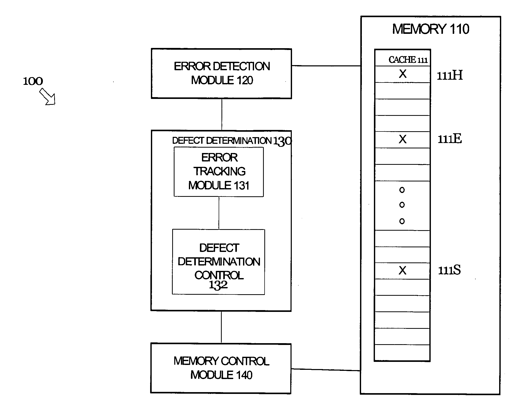
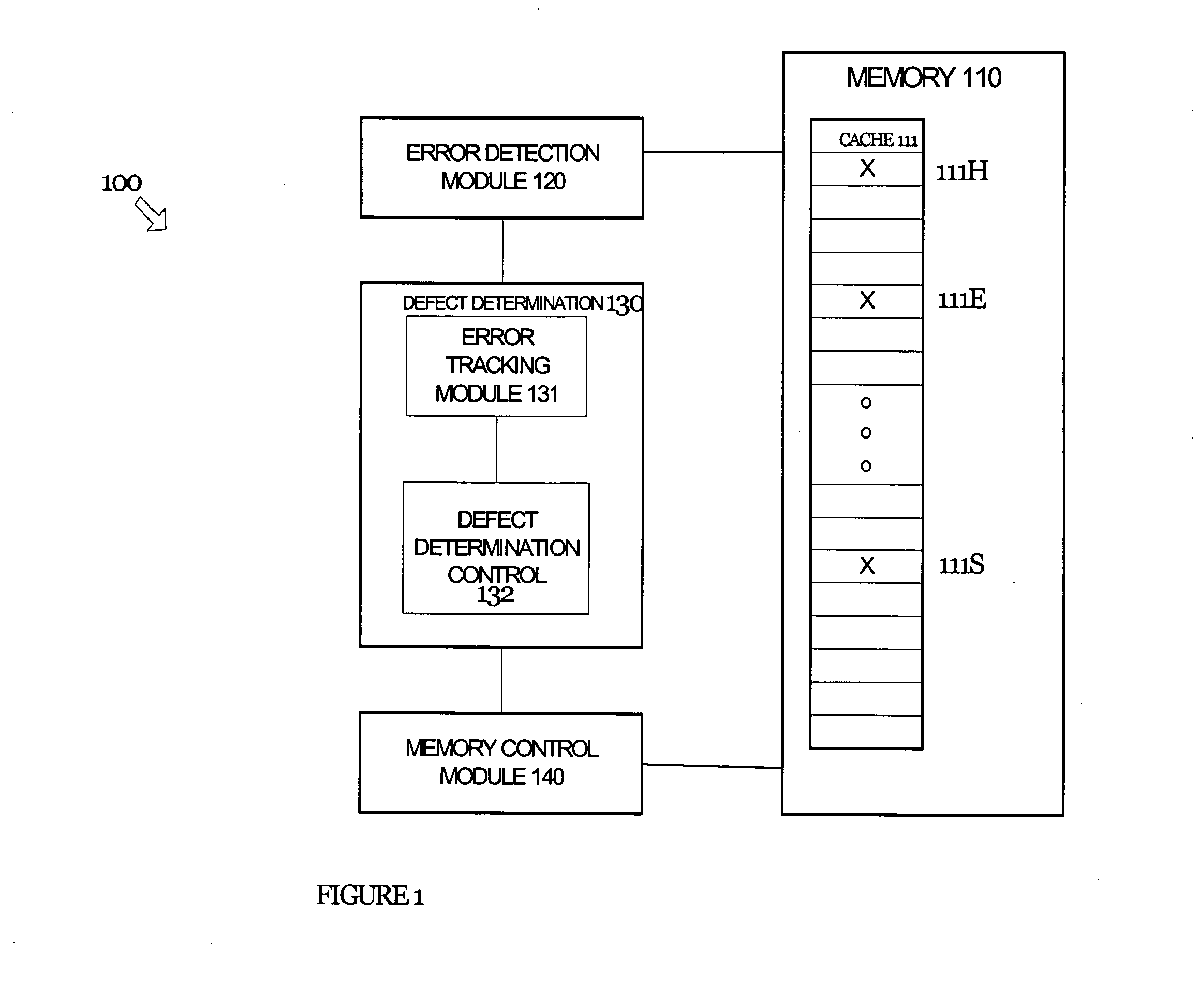
[0011]In general, systems and methods are disclosed herein for identifying and avoiding attempts to access a defective portion of memory. That is, techniques are provided for detecting a defect in a portion of memory and dynamically avoiding future attempts to access the defective portion of memory. More specifically, the following techniques detect and avoid both hard and erratic errors. The embodiments described herein are described in the context of a cache memory in a microprocessor, but are not so limited. The same techniques and teachings of the present invention may easily be applied to other types of circuits or semiconductor devices containing memory that may benefit from reliable access to memory. In addition, the methods of the present invention may be implemented in software or hardware as one of ordinary skill in the art will appreciate.

[0012]In the following description, for purposes of explanation, numerous specific details are set forth in order to provide a thorough...


PUM


Abstract

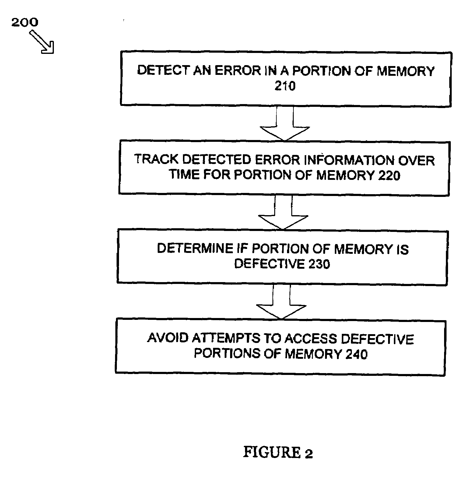
An apparatus and methods are disclosed herein for identifying and avoiding attempts to access a defective portion of memory. Errors associated with portions of memory, such as a cache memory, are tracked over time enabling detection of both hard and erratic errors. Based on the number of errors tracked over time for a portion of memory, it is determined if the portion of memory is defective. In response to determining portion of memory is defective, the portion of memory is disabled. The portion of memory may be flushed and moved before being disable. Additionally, disabling the portion of memory may be conditioned upon determining if it is allowable to disable the portion of memory.

Description

[0001]The present patent application is a Divisional Application of application Ser. No. 11 / 472,870, filed Jun. 21, 2006.BACKGROUND OF THE INVENTION[0002]Data storage, referred to generically herein as “memory,” is commonly implemented in computer systems. Computer systems may employ a multi-level hierarchy of memory, with relatively fast, expensive but limited-capacity memory at the lowest level of the hierarchy and proceeding to relatively slower, lower cost but higher-capacity memory at the highest level of the hierarchy. The hierarchy may include a fast memory called a cache, either physically integrated within a processor or mounted physically close to the processor for speed. In addition, the computer system may use multiple levels of caches.[0003]From time-to-time a defect may occur within a portion of memory. Such defect may occur and be detected during manufacturing (or “fabricating”) the memory, or such defect may be a latent defect that is not observed until after the mem...

Claims


Application Information

Patent Timeline
Patent Type & Authority Applications(United States)
IPC IPC(8): G11C29/00G06F11/20
CPCG06F11/1024G11C29/52G11C2029/0409G11C29/883G11C29/88
Inventor SRIVASTAVA, DURGESHSHOEMAKER, JONATHANBENOIT, JOHN
Owner INTEL CORP
Learn More