Aircraft Passenger Seat

Inactive Publication Date: 2009-12-10
BRISTISH AIRWAYS PLC
View PDF81 Cites 83 Cited by
  • Summary
  • Abstract
  • Description
  • Claims
  • Application Information

AI Technical Summary

Benefits of technology

[0016]Preferably, the mechanism is also able to secure the support surface in a third, substantially horizontal position displaced in a vertical direction from the first position. Preferably, the third position is also displaced in a horizontal direction from the first position. An advantage of this arrangement is that the support surface may act as a leg rest for the passenger both in a semi-reclined and a sleeping position, while also acting as a foot rest for the passenger in an upright sitting position.
[0017]Preferably, the mechanism is operable to move the support surface to a substantially vertical, stowed position. An

Problems solved by technology

Passenger seats for aircraft are subject to stringent design constraints, many of which are not applicable to seats for other vehicle types.
One problem is the need to meet the relevant safety standards for aircraft passenger seats, such as the 16 g test that requires seats to survive deceleration of 16 g in a takeoff/landing position.
Another problem is the need to minimize the weight of the seat, since carrying extra weight on an aircraft increases fuel consumption and therefore monetary and environmental cost.
Another problem relates to th

Method used


Image

  • Aircraft Passenger Seat
  • Aircraft Passenger Seat
  • Aircraft Passenger Seat

Examples


first embodiment

[0079]FIGS. 7a and 7b show a first embodiment of the armrest mechanism in the raised and lowered positions respectively. In the raised position, the lower surface of the armrest support 9a, 9b rests on a pin 30, moveable reciprocally along a substantially vertical arcuate track 31 in the upper frame 11 and connected by a first linkage 32 to a fixed first pivot 33 located on the upper frame 11 forward of the armrest support 9a, 9b, and connected by a second linkage 34 to a second pivot 35 moveable reciprocally along a substantially horizontal arcuate track 36 in the upper frame 11. As the second pivot 35 moves forward along the horizontal arcuate track 36 from the position shown in FIG. 7a to that shown in FIG. 7b, the pin 30 falls along the substantially vertical arcuate track 31 as the first and second linkages 32, 34 rotate clockwise, and the armrest support 9a, 9b falls under gravity, following the pin 30, until the armrest support 9a, 9b comes to rest on stops 37. The lower surf...

second embodiment

[0081]A second embodiment of the armrest mechanism is shown in FIGS. 7c and 7d. Similar parts to the first embodiment carry the same reference numerals. In this embodiment, the first linkage 32 is not present, and the armrest mechanism has a single linkage 34, the lower end of which comprises the pivot 35 moveable reciprocally along the substantially horizontal arcuate track 36 in the upper frame 11. The upper end of the single linkage 34 comprises the pin 30 which is moveable along the substantially vertical arcuate track 31.

[0082]As the seat is moved into an upright position, a lifter blade 38 fixed to the drive rail 13 abuts the pivot 35 and pushes it rearwardly along the substantially horizontal arcuate track 36 so that the pin 30 rises in the substantially vertical arcuate track 31 and pushes the lower surface of the armrest support 9a, 9b into the raised position. As the seat reclines, the pivot 35 is biased against the lifter blade 38 and moves forwards with the lifter blade ...

third embodiment

[0084]FIGS. 7e and 7f show a third embodiment of the armrest mechanism in the raised and lowered positions respectively. Similar parts to the first and second embodiments carry the same reference numerals and their description will not be repeated except where necessary.

[0085]In common with the first embodiment, the armrest mechanism of the third embodiment comprises first and second linkages 32, 34, rather than the single linkage 34 of the second embodiment. The first and second linkages 32, 34 are biased towards a collapsed position as shown in FIG. 7f, whereby the armrest support 9b is biased into the lowered position. In this example, the bias is applied by springs 32′, 34′ connected between the upper frame 11 and the first and second linkages 32, 34 respectively.

[0086]The armrest mechanism is moved from the lowered position to the raised position of FIG. 7a by lifter blade 38 (not shown) similar to that of the second embodiment, which abuts the second pivot 35 and moves it alon...


PUM


Abstract

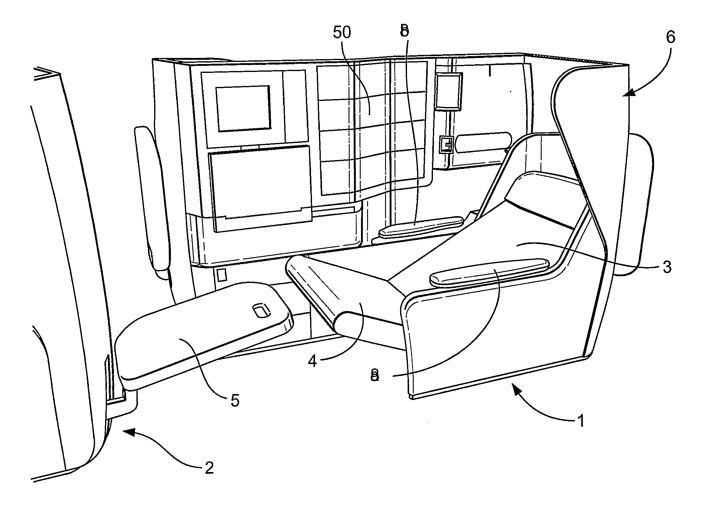
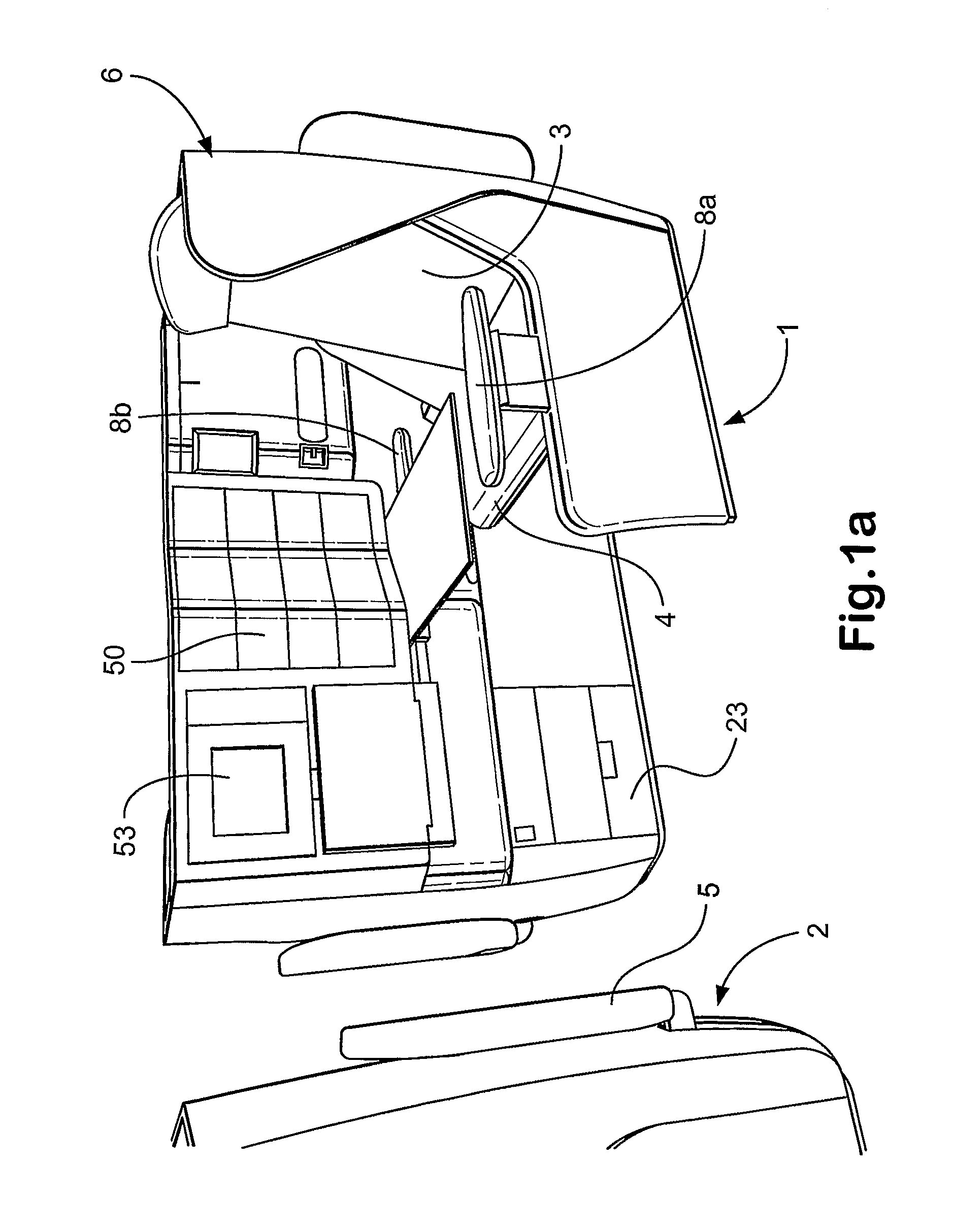
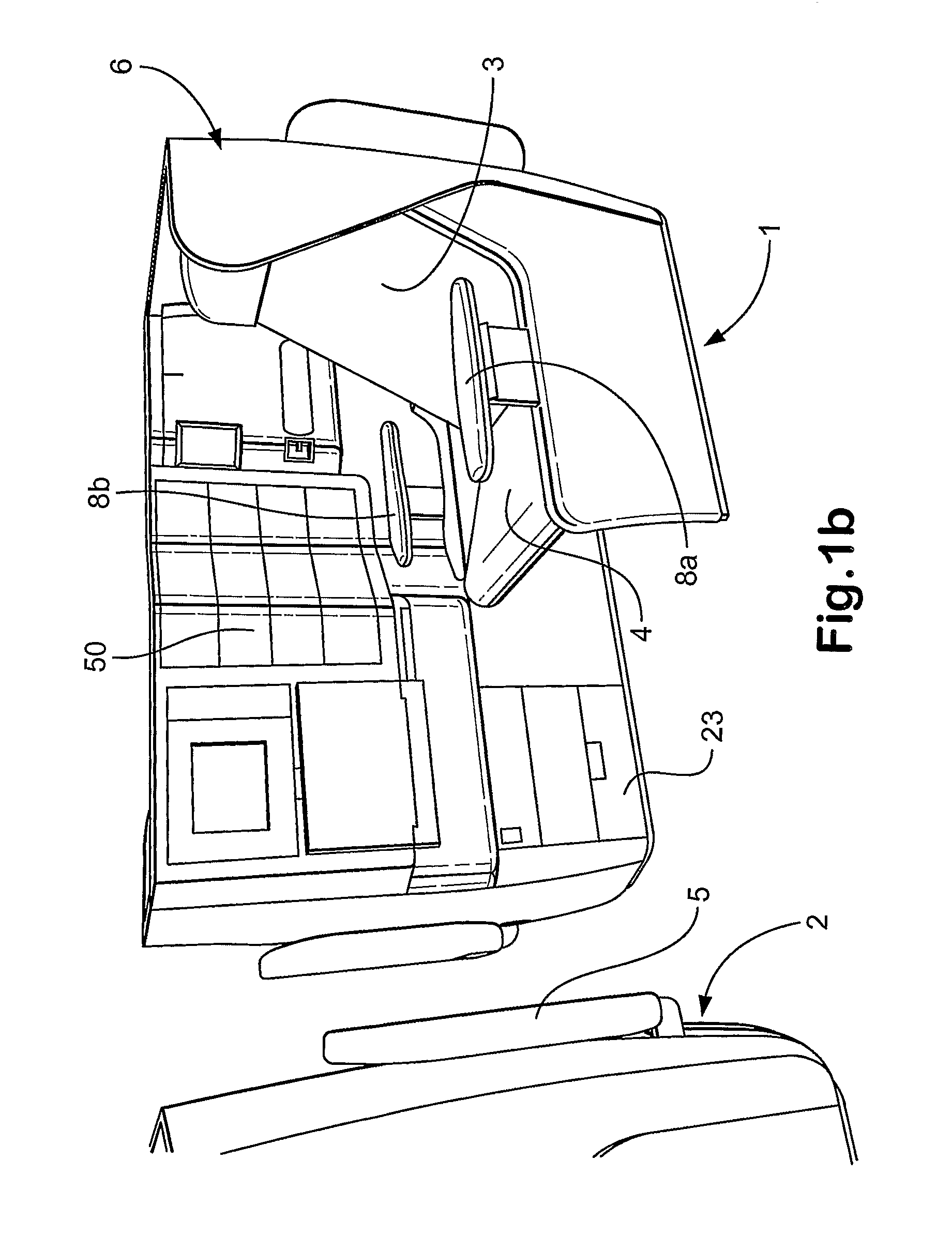
An aircraft passenger seat comprises a primary seat (1) having a seat back (3) and a seat pan (4), and a secondary support surface (5) located or locatable opposite the primary seat (1), the passenger seat being able to adopt each of an upright configuration, a reclined configuration and a substantially flat configuration, such that in the reclined configuration, the primary seat (1) is reclined relative to the upright configuration and the secondary support surface (5) is angled upwardly towards the primary seat (1) so as to support the lower leg(s) of a passenger seated in the primary seat (1); and in the substantially flat configuration, the secondary support surface (5) is substantially horizontal and the seat back (3), the seat pan (4) and the secondary support surface (5) form a substantially flat and continuous surface wherein the secondary support surface (5) is rotatable about an axis between the reclined and substantially flat configurations, said axis being translated between the reclined and substantially flat configurations.

Description

[0001]The present invention relates to an aircraft passenger seat, particularly but not exclusively to an aircraft sleeper seat convertible into a substantially flat bed.BACKGROUND TO THE INVENTION[0002]Examples of prior art aircraft sleeper seats are disclosed in the applicant's patent publications WO 96 / 18537 and WO00 / 21831, embodiments of which include the current British Airways First and Club World seats respectively. Both of these seats can be converted into a flat, horizontal bed, and have enjoyed great commercial success. However, there is intense competition to provide ever-greater comfort and space for aircraft passengers.[0003]Passenger seats for aircraft are subject to stringent design constraints, many of which are not applicable to seats for other vehicle types. One problem is the need to meet the relevant safety standards for aircraft passenger seats, such as the 16 g test that requires seats to survive deceleration of 16 g in a takeoff / landing position. Another probl...

Claims


Application Information

Patent Timeline
IPC IPC(8): B64D11/06B60N2/22B60N2/34B60N3/06B60N2/46B60N2/44B60N2/75B60N2/90
CPCB64D11/06B64D11/064B64D11/0606B64D11/0643B64D11/0604B64D11/0646B64D11/0641
Inventor DARBYSHIRE, MARTINROUND, MATTHEWHERRING, III, ASA DANCYWALDRIP, DENNIS ISAACSCHATELL, MARCWYSS, ALENHALL, GREGORYSUTCAVAGE, WALTERLOVINGOOD, JOHNALFORD, DAN
Owner BRISTISH AIRWAYS PLC
Why Eureka
Try Eureka